
User's Manual
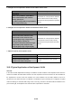


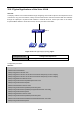


Table Of Contents
- Chapter 1 INTRODUCTION
- Chapter 2 INSTALLATION
- Chapter 3 Switch Management
- Chapter 4 Basic Switch Configuration
- Chapter 5 File System Operations
- Chapter 6 Cluster Configuration
- Chapter 7 Port Configuration
- Chapter 8 Port Isolation Function Configuration
- Chapter 9 Port Loopback Detection Function Configuration
- Chapter 10 ULDP Function Configuration
- Chapter 11 LLDP Function Operation Configuration
- Chapter 12 Port Channel Configuration
- Chapter 13 Jumbo Configuration
- Chapter 14 EFM OAM Configuration
- Chapter 15 VLAN Configuration
- Chapter 16 MAC Table Configuration
- Chapter 17 MSTP Configuration
- Chapter 18 QoS Configuration
- Chapter 19 Flow-based Redirection
- Chapter 20 Egress QoS Configuration
- Chapter 21 Flexible Q-in-Q Configuration
- Chapter 22 Layer 3 Forward Configuration
- Chapter 23 ARP Scanning Prevention Function Configuration
- Chapter 24 Prevent ARP, ND Spoofing Configuration
- Chapter 25 ARP GUARD Configuration
- Chapter 26 ARP Local Proxy Configuration
- Chapter 27 Gratuitous ARP Configuration
- Chapter 28 Keepalive Gateway Configuration
- Chapter 29 DHCP Configuration
- Chapter 30 DHCPv6 Configuration
- Chapter 31 DHCP option 82 Configuration
- Chapter 32 DHCPv6 option37, 38
- Chapter 33 DHCP Snooping Configuration
- Chapter 34 Routing Protocol Overview
- Chapter 35 Static Route
- Chapter 36 RIP
- Chapter 37 RIPng
- Chapter 38 OSPF
- Chapter 39 OSPFv3
- Chapter 40 BGP
- 40.1 Introduction to BGP
- 40.2 BGP Configuration Task List
- 40.3 Configuration Examples of BGP
- 40.3.1 Examples 1: configure BGP neighbor
- 40.3.2 Examples 2: configure BGP aggregation
- 40.3.3 Examples 3: configure BGP community attributes
- 40.3.4 Examples 4: configure BGP confederation
- 40.3.5 Examples 5: configure BGP route reflector
- 40.3.6 Examples 6: configure MED of BGP
- 40.3.7 Examples 7: example of BGP VPN
- 40.4 BGP Troubleshooting
- Chapter 41 MBGP4+
- Chapter 42 Black Hole Routing Manual
- Chapter 43 GRE Tunnel Configuration
- Chapter 44 ECMP Configuration
- Chapter 45 BFD
- Chapter 46 BGP GR
- Chapter 47 OSPF GR
- Chapter 48 IPv4 Multicast Protocol
- 48.1 IPv4 Multicast Protocol Overview
- 48.2 PIM-DM
- 48.3 PIM-SM
- 48.4 MSDP Configuration
- 48.4.1 Introduction to MSDP
- 48.4.2 Brief Introduction to MSDP Configuration Tasks
- 48.4.3 Configuration of MSDP Basic Function
- 48.4.4 Configuration of MSDP Entities
- 48.4.5 Configuration of Delivery of MSDP Packet
- 48.4.6 Configuration of Parameters of SA-cache
- 48.4.7 MSDP Configuration Examples
- 48.4.8 MSDP Troubleshooting
- 48.5 ANYCAST RP Configuration
- 48.6 PIM-SSM
- 48.7 DVMRP
- 48.8 DCSCM
- 48.9 IGMP
- 48.10 IGMP Snooping
- 48.11 IGMP Proxy Configuration
- Chapter 49 IPv6 Multicast Protocol
- Chapter 50 Multicast VLAN
- Chapter 51 ACL Configuration
- Chapter 52 802.1x Configuration
- 52.1 Introduction to 802.1x
- 52.2 802.1x Configuration Task List
- 52.3 802.1x Application Example
- 52.4 802.1x Troubleshooting
- Chapter 53 The Number Limitation Function of Port, MAC in VLAN and IP Configuration
- 53.1 Introduction to the Number Limitation Function of Port, MAC in VLAN and IP
- 53.2 The Number Limitation Function of Port, MAC in VLAN and IP Configuration Task Sequence
- 53.3 The Number Limitation Function of Port, MAC in VLAN and IP Typical Examples
- 53.4 The Number Limitation Function of Port, MAC in VLAN and IP Troubleshooting Help
- Chapter 54 Operational Configuration of AM Function
- Chapter 55 TACACS+ Configuration
- Chapter 56 RADIUS Configuration
- Chapter 57 SSL Configuration
- Chapter 58 IPv6 Security RA Configuration
- Chapter 59 VLAN-ACL Configuration
- Chapter 60 MAB Configuration
- Chapter 61 PPPoE Intermediate Agent Configuration
- Chapter 62 SAVI Configuration
- Chapter 63 Web Portal Configuration
- Chapter 64 VRRP Configuration
- Chapter 65 IPv6 VRRPv3 Configuration
- Chapter 66 MRPP Configuration
- Chapter 67 ULPP Configuration
- Chapter 68 ULSM Configuration
- Chapter 69 Mirror Configuration
- Chapter 70 RSPAN Configuration
- Chapter 71 sFlow Configuration
- Chapter 72 SNTP Configuration
- Chapter 73 NTP Function Configuration
- Chapter 74 DNSv4/v6 Configuration
- Chapter 75 Summer Time Configuration
- Chapter 76 Monitor and Debug
- Chapter 77 Reload Switch after Specified Time
- Chapter 78 Debugging and Diagnosis for Packets Received and Sent by CPU
- Chapter 79 VSF
- Chapter 80 PoE Configuration
- Chapter 81 SWITCH OPERATION
- Chapter 82 TROUBLESHOOTING
- Chapter 83 APPENDIX A
- Chapter 84 GLOSSARY

16-35
The topology of the figure above: 4 PCs connected to switch, where PC1 and PC2 belongs to a same physical
segment (same collision domain), the physical segment connects to port 1/0/5 of switch; PC3 and PC4
belongs to the same physical segment that connects to port 1/0/12 of switch.
The initial MAC table contains no address mapping entries. Take the communication of PC1 and PC3 as an
example, the MAC address learning process is as follow:
1. When PC1 sends message to PC3, the switch receives the source MAC address
00-01-11-11-11-11 from this message, the mapping entry of 00-01-11-11-11-11 and port 1/0/5 is
added to the switch MAC table.
2. At the same time, the switch learns the message is destined to 00-01-33-33-33-33, as the MAC
table contains only a mapping entry of MAC address 00-01-11-11-11-11 and port1/0/5, and no port
mapping for 00-01-33-33-33-33 present, the switch broadcast this message to all the ports in the
switch (assuming all ports belong to the default VLAN1).
3. PC3 and PC4 on port 1/0/12 receive the message sent by PC1, but PC4 will not reply, as the
destination MAC address is 00-01-33-33-33-33, only PC3 will reply to PC1. When port 1/0/12
receives the message sent by PC3, a mapping entry for MAC address 00-01-33-33-33-33 and port
1/0/12 is added to the MAC table.
4. Now the MAC table has two dynamic entries, MAC address 00-01-11-11-11-11 - port 1/0/5 and
00-01-33-33-33-33 -port1/0/12.
5. After the communication between PC1 and PC3, the switch does not receive any message sent
from PC1 and PC3. And the MAC address mapping entries in the MAC table are deleted in 300 to
2*300 seconds (ie, in single to double aging time). The 300 seconds here is the default aging time
for MAC address entry in switch. Aging time can be modified in switch.
16.1.2 Forward or Filter
The switch will forward or filter received data frames according to the MAC table. Take the above figure as an
example, assuming switch have learnt the MAC address of PC1 and PC3, and the user manually configured
the mapping relationship for PC2 and PC4 to ports. The MAC table of switch will be:
MAC Address
Port number
Entry added by
00-01-11-11-11-11
1/0/5
Dynamic learning
00-01-22-22-22-22
1/0/5
Static configuration
00-01-33-33-33-33
1/0/12
Dynamic learning
00-01-44-44-44-44
1/0/12
Static configuration
1. Forward data according to the MAC table
If PC1 sends a message to PC3, the switch will forward the data received on port 1/0/5 from port1/0/12.
2. Filter data according to the MAC table
If PC1 sends a message to PC2, the switch, on checking the MAC table, will find PC2 and PC1 are in the
same physical segment and filter the message (i.e. drop this message).