
User's Manual


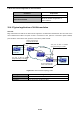


Table Of Contents
- Chapter 1 INTRODUCTION
- Chapter 2 INSTALLATION
- Chapter 3 Switch Management
- Chapter 4 Basic Switch Configuration
- Chapter 5 File System Operations
- Chapter 6 Cluster Configuration
- Chapter 7 Port Configuration
- Chapter 8 Port Isolation Function Configuration
- Chapter 9 Port Loopback Detection Function Configuration
- Chapter 10 ULDP Function Configuration
- Chapter 11 LLDP Function Operation Configuration
- Chapter 12 Port Channel Configuration
- Chapter 13 Jumbo Configuration
- Chapter 14 EFM OAM Configuration
- Chapter 15 VLAN Configuration
- Chapter 16 MAC Table Configuration
- Chapter 17 MSTP Configuration
- Chapter 18 QoS Configuration
- Chapter 19 Flow-based Redirection
- Chapter 20 Egress QoS Configuration
- Chapter 21 Flexible Q-in-Q Configuration
- Chapter 22 Layer 3 Forward Configuration
- Chapter 23 ARP Scanning Prevention Function Configuration
- Chapter 24 Prevent ARP, ND Spoofing Configuration
- Chapter 25 ARP GUARD Configuration
- Chapter 26 ARP Local Proxy Configuration
- Chapter 27 Gratuitous ARP Configuration
- Chapter 28 Keepalive Gateway Configuration
- Chapter 29 DHCP Configuration
- Chapter 30 DHCPv6 Configuration
- Chapter 31 DHCP option 82 Configuration
- Chapter 32 DHCPv6 option37, 38
- Chapter 33 DHCP Snooping Configuration
- Chapter 34 Routing Protocol Overview
- Chapter 35 Static Route
- Chapter 36 RIP
- Chapter 37 RIPng
- Chapter 38 OSPF
- Chapter 39 OSPFv3
- Chapter 40 BGP
- 40.1 Introduction to BGP
- 40.2 BGP Configuration Task List
- 40.3 Configuration Examples of BGP
- 40.3.1 Examples 1: configure BGP neighbor
- 40.3.2 Examples 2: configure BGP aggregation
- 40.3.3 Examples 3: configure BGP community attributes
- 40.3.4 Examples 4: configure BGP confederation
- 40.3.5 Examples 5: configure BGP route reflector
- 40.3.6 Examples 6: configure MED of BGP
- 40.3.7 Examples 7: example of BGP VPN
- 40.4 BGP Troubleshooting
- Chapter 41 MBGP4+
- Chapter 42 Black Hole Routing Manual
- Chapter 43 GRE Tunnel Configuration
- Chapter 44 ECMP Configuration
- Chapter 45 BFD
- Chapter 46 BGP GR
- Chapter 47 OSPF GR
- Chapter 48 IPv4 Multicast Protocol
- 48.1 IPv4 Multicast Protocol Overview
- 48.2 PIM-DM
- 48.3 PIM-SM
- 48.4 MSDP Configuration
- 48.4.1 Introduction to MSDP
- 48.4.2 Brief Introduction to MSDP Configuration Tasks
- 48.4.3 Configuration of MSDP Basic Function
- 48.4.4 Configuration of MSDP Entities
- 48.4.5 Configuration of Delivery of MSDP Packet
- 48.4.6 Configuration of Parameters of SA-cache
- 48.4.7 MSDP Configuration Examples
- 48.4.8 MSDP Troubleshooting
- 48.5 ANYCAST RP Configuration
- 48.6 PIM-SSM
- 48.7 DVMRP
- 48.8 DCSCM
- 48.9 IGMP
- 48.10 IGMP Snooping
- 48.11 IGMP Proxy Configuration
- Chapter 49 IPv6 Multicast Protocol
- Chapter 50 Multicast VLAN
- Chapter 51 ACL Configuration
- Chapter 52 802.1x Configuration
- 52.1 Introduction to 802.1x
- 52.2 802.1x Configuration Task List
- 52.3 802.1x Application Example
- 52.4 802.1x Troubleshooting
- Chapter 53 The Number Limitation Function of Port, MAC in VLAN and IP Configuration
- 53.1 Introduction to the Number Limitation Function of Port, MAC in VLAN and IP
- 53.2 The Number Limitation Function of Port, MAC in VLAN and IP Configuration Task Sequence
- 53.3 The Number Limitation Function of Port, MAC in VLAN and IP Typical Examples
- 53.4 The Number Limitation Function of Port, MAC in VLAN and IP Troubleshooting Help
- Chapter 54 Operational Configuration of AM Function
- Chapter 55 TACACS+ Configuration
- Chapter 56 RADIUS Configuration
- Chapter 57 SSL Configuration
- Chapter 58 IPv6 Security RA Configuration
- Chapter 59 VLAN-ACL Configuration
- Chapter 60 MAB Configuration
- Chapter 61 PPPoE Intermediate Agent Configuration
- Chapter 62 SAVI Configuration
- Chapter 63 Web Portal Configuration
- Chapter 64 VRRP Configuration
- Chapter 65 IPv6 VRRPv3 Configuration
- Chapter 66 MRPP Configuration
- Chapter 67 ULPP Configuration
- Chapter 68 ULSM Configuration
- Chapter 69 Mirror Configuration
- Chapter 70 RSPAN Configuration
- Chapter 71 sFlow Configuration
- Chapter 72 SNTP Configuration
- Chapter 73 NTP Function Configuration
- Chapter 74 DNSv4/v6 Configuration
- Chapter 75 Summer Time Configuration
- Chapter 76 Monitor and Debug
- Chapter 77 Reload Switch after Specified Time
- Chapter 78 Debugging and Diagnosis for Packets Received and Sent by CPU
- Chapter 79 VSF
- Chapter 80 PoE Configuration
- Chapter 81 SWITCH OPERATION
- Chapter 82 TROUBLESHOOTING
- Chapter 83 APPENDIX A
- Chapter 84 GLOSSARY

15-21
15.3 Dot1q-tunnel Configuration
15.3.1 Introduction to Dot1q-tunnel
Dot1q-tunnel is also called Q-in-Q (802.1Q-in-802.1Q), which is an expansion of 802.1Q. Its dominating idea
is encapsulating the customer VLAN tag (CVLAN tag) to the service provider VLAN tag (SPVLAN tag).
Carrying the two VLAN tags the packet is transmitted through the backbone network of the ISP internet, so to
provide a simple layer-2 tunnel for the users. It is simple and easy to manage, applicable only by static
configuration, and especially adaptive to small office network or small scale metropolitan area network using
layer-3 switch as backbone equipment.
Figure 15-6 Dot1q-tunnel based Internetworking mode
As shown in above, after being enabled on the user port, dot1q-tunnel assigns each user an SPVLAN
identification (SPVID). Here the identification of user is 3. Same SPVID should be assigned for the same
network user on different PEs. When packet reaches PE1 from CE1, it carries the VLAN tag 200-300 of the
user internal network. Since the dot1q-tunnel function is enabled, the user port on PE1 will add on the packet
another VLAN tag, of which the ID is the SPVID assigned to the user. Afterwards, the packet will only be
transmitted in VLAN3 when traveling in the ISP internet network while carrying two VLAN tags (the inner tag is
added when entering PE1, and the outer is SPVID), whereas the VLAN information of the user network is
open to the provider network. When the packet reaches PE2 and before being forwarded to CE2 from the
client port on PE2, the outer VLAN tag is removed, then the packet CE2 receives is absolutely identical to the
one sent by CE1. For the user, the role the operator network plays between PE1 and PE2, is to provide a
reliable layer-2 link.
The technology of Dot1q-tuunel provides the ISP internet the ability of supporting many client VLANs by only
one VLAN of their selves. Both the ISP internet and the clients can configure their own VLAN independently.
It is obvious that, the dot1q-tunnel function has got following characteristics:
Applicable through simple static configuration, no complex configuration or maintenance to be needed.
Operators will only have to assign one SPVID for each user, which increases the number of concurrent
supportable users; while the users has got the ultimate freedom in selecting and managing the VLAN
IDs (select within 1~4096 at users’ will).
SP networks
P
PE1
PE2
CE1
CE2
Trunk connection
Trunk connection
Unsymmetrical
connection
Unsymmetrical
connection
Customer
networks1
Customer
networks2
On the customer port
Trunk VLAN 200-300
This port on PE1 is enabled
QinQ and belong to VLAN3
On the customer port
Trunk VLAN 200-300
This port on PE1 is enabled
QinQ and belong to VLAN3