
SGS-6341-Series User Manual
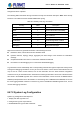
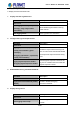
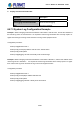
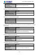
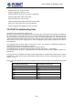
Table Of Contents
- Chapter 1 INTRODUCTION
- Chapter 2 INSTALLATION
- Chapter 3 Switch Management
- Chapter 4 Basic Switch Configuration
- Chapter 5 File System Operations
- Chapter 6 Cluster Configuration
- Chapter 7 Port Configuration
- Chapter 8 Port Isolation Function Configuration
- Chapter 9 Port Loopback Detection Function Configuration
- Chapter 10 ULDP Function Configuration
- Chapter 11 LLDP Function Operation Configuration
- Chapter 12 Port Channel Configuration
- Chapter 13 MTU Configuration
- Chapter 14 EFM OAM Configuration
- Chapter 15 PORT SECURITY
- Chapter 16 DDM Configuration
- Chapter 17 LLDP-MED
- Chapter 18 bpdu-tunnel Configuration
- Chapter 19 EEE Energy-saving Configuration
- Chapter 20 VLAN Configuration
- Chapter 21 MAC Table Configuration
- Chapter 22 MSTP Configuration
- Chapter 23 QoS Configuration
- Chapter 24 Flow-based Redirection
- Chapter 25 Flexible Q-in-Q Configuration
- Chapter 26 Layer 3 Management Configuration
- Chapter 27 ARP Scanning Prevention Function Configuration
- Chapter 28 Prevent ARP Spoofing Configuration
- Chapter 29 ARP GUARD Configuration
- Chapter 30 Gratuitous ARP Configuration
- Chapter 31 DHCP Configuration
- Chapter 32 DHCPv6 Configuration
- Chapter 33 DHCP Option 82 Configuration
- Chapter 34 DHCP Option 60 and option 43
- Chapter 35 DHCPv6 Options 37, 38
- Chapter 36 DHCP Snooping Configuration
- Chapter 37 DHCP Snooping Option 82 Configuration
- Chapter 38 IPv4 Multicast Protocol
- Chapter 39 IPv6 Multicast Protocol
- Chapter 40 Multicast VLAN
- Chapter 41 ACL Configuration
- Chapter 42 802.1x Configuration
- 42.1 Introduction to 802.1x
- 42.2 802.1x Configuration Task List
- 42.3 802.1x Application Example
- 42.4 802.1x Troubleshooting
- Chapter 43 The Number Limitation Function of MAC and IP in Port, VLAN Configuration
- Chapter 44 Operational Configuration of AM Function
- Chapter 45 Security Feature Configuration
- 45.1 Introduction to Security Feature
- 45.2 Security Feature Configuration
- 45.2.1 Prevent IP Spoofing Function Configuration Task Sequence
- 45.2.2 Prevent TCP Unauthorized Label Attack Function Configuration Task Sequence
- 45.2.3 Anti Port Cheat Function Configuration Task Sequence
- 45.2.4 Prevent TCP Fragment Attack Function Configuration Task Sequence
- 45.2.5 Prevent ICMP Fragment Attack Function Configuration Task Sequence
- 45.3 Security Feature Example
- Chapter 46 TACACS+ Configuration
- Chapter 47 RADIUS Configuration
- Chapter 48 SSL Configuration
- Chapter 49 IPv6 Security RA Configuration
- Chapter 50 MAB Configuration
- Chapter 51 PPPoE Intermediate Agent Configuration
- Chapter 52 Web Portal Configuration
- Chapter 53 VLAN-ACL Configuration
- Chapter 54 SAVI Configuration
- Chapter 55 MRPP Configuration
- Chapter 56 ULPP Configuration
- Chapter 57 ULSM Configuration
- Chapter 58 Mirror Configuration
- Chapter 59 sFlow Configuration
- Chapter 60 RSPAN Configuration
- Chapter 61 ERSPAN
- Chapter 62 SNTP Configuration
- Chapter 63 NTP Function Configuration
- Chapter 64 Summer Time Configuration
- Chapter 65 DNSv4/v6 Configuration
- Chapter 66 Monitor and Debug
- Chapter 67 Reload Switch after Specified Time
- Chapter 68 Debugging and Diagnosis for Packets Received and Sent by CPU
- Chapter 69 Dying Gasp Configuration
- Chapter 70 PoE Configuration

70-76
Switch(Config)# power inline enable
Globally set the max. power to 370W:
Switch(Config)# power inline max. 370
Globally enable the priority policy of power management:
Switch(Config)# power inline police enable
Set the priority of Port 1/0/2 to critical:
Switch(Config-Ethernet1/0/2)# power inline priority critical
Set the max. output power of Port 1/0/6 to 9000mW:
Switch(Config-Ethernet1/0/6)#power inline max. 9000
70.4 PoE Troubleshooting Help
If problems occur on using PoE, please check:
When the global value of Power Remaining is less than 15W, due to the power source protection mechanism,
the power supply to new PDs will be cut off in first-come-first-serve mode, while the existing low-priority
devices will also be disconnected in priority policy mode. If the Power Remaining is over 15W, say 16W, any
newly connected device with a power no more than 15W can get its power supply normally, without affecting
other devices. Such a power supply buffer of 15W is designed for power source protection, and calls for
special attention.
The displayed value of power might over the value of max. This involves the relationship between the
displayed power and the actual power, for instance:
The power set on the port: A, represents the actual output PoE power
The displayed power: B, represents the total power of the port (total current × total voltage)
The power loss set on the port: C, represents power loss of the internal Sensor ohmic resistance, MosFet etc.
Then: B=A+C
If the power is set as A=500mW, according to the following table, the compensating current will be I=2.44mA
(500mW/50V=10mA assuming the current working voltage is 50V), plus the compensating power C=50V×
2.44mA=122mA
B=A+C=500+122=622mW. So, only when the displayed power reaches 622mW, the PD will be disconnected
Table:
Max. Working Current (mA) Compensating Current (mA)
50 2.44
100 4.88
150 9.76
200 17.08
250 24.41
350 31.73
User’s Manual of SGS-6341 series