
SGS-6341-Series User Manual
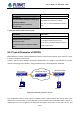
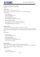

Table Of Contents
- Chapter 1 INTRODUCTION
- Chapter 2 INSTALLATION
- Chapter 3 Switch Management
- Chapter 4 Basic Switch Configuration
- Chapter 5 File System Operations
- Chapter 6 Cluster Configuration
- Chapter 7 Port Configuration
- Chapter 8 Port Isolation Function Configuration
- Chapter 9 Port Loopback Detection Function Configuration
- Chapter 10 ULDP Function Configuration
- Chapter 11 LLDP Function Operation Configuration
- Chapter 12 Port Channel Configuration
- Chapter 13 MTU Configuration
- Chapter 14 EFM OAM Configuration
- Chapter 15 PORT SECURITY
- Chapter 16 DDM Configuration
- Chapter 17 LLDP-MED
- Chapter 18 bpdu-tunnel Configuration
- Chapter 19 EEE Energy-saving Configuration
- Chapter 20 VLAN Configuration
- Chapter 21 MAC Table Configuration
- Chapter 22 MSTP Configuration
- Chapter 23 QoS Configuration
- Chapter 24 Flow-based Redirection
- Chapter 25 Flexible Q-in-Q Configuration
- Chapter 26 Layer 3 Management Configuration
- Chapter 27 ARP Scanning Prevention Function Configuration
- Chapter 28 Prevent ARP Spoofing Configuration
- Chapter 29 ARP GUARD Configuration
- Chapter 30 Gratuitous ARP Configuration
- Chapter 31 DHCP Configuration
- Chapter 32 DHCPv6 Configuration
- Chapter 33 DHCP Option 82 Configuration
- Chapter 34 DHCP Option 60 and option 43
- Chapter 35 DHCPv6 Options 37, 38
- Chapter 36 DHCP Snooping Configuration
- Chapter 37 DHCP Snooping Option 82 Configuration
- Chapter 38 IPv4 Multicast Protocol
- Chapter 39 IPv6 Multicast Protocol
- Chapter 40 Multicast VLAN
- Chapter 41 ACL Configuration
- Chapter 42 802.1x Configuration
- 42.1 Introduction to 802.1x
- 42.2 802.1x Configuration Task List
- 42.3 802.1x Application Example
- 42.4 802.1x Troubleshooting
- Chapter 43 The Number Limitation Function of MAC and IP in Port, VLAN Configuration
- Chapter 44 Operational Configuration of AM Function
- Chapter 45 Security Feature Configuration
- 45.1 Introduction to Security Feature
- 45.2 Security Feature Configuration
- 45.2.1 Prevent IP Spoofing Function Configuration Task Sequence
- 45.2.2 Prevent TCP Unauthorized Label Attack Function Configuration Task Sequence
- 45.2.3 Anti Port Cheat Function Configuration Task Sequence
- 45.2.4 Prevent TCP Fragment Attack Function Configuration Task Sequence
- 45.2.5 Prevent ICMP Fragment Attack Function Configuration Task Sequence
- 45.3 Security Feature Example
- Chapter 46 TACACS+ Configuration
- Chapter 47 RADIUS Configuration
- Chapter 48 SSL Configuration
- Chapter 49 IPv6 Security RA Configuration
- Chapter 50 MAB Configuration
- Chapter 51 PPPoE Intermediate Agent Configuration
- Chapter 52 Web Portal Configuration
- Chapter 53 VLAN-ACL Configuration
- Chapter 54 SAVI Configuration
- Chapter 55 MRPP Configuration
- Chapter 56 ULPP Configuration
- Chapter 57 ULSM Configuration
- Chapter 58 Mirror Configuration
- Chapter 59 sFlow Configuration
- Chapter 60 RSPAN Configuration
- Chapter 61 ERSPAN
- Chapter 62 SNTP Configuration
- Chapter 63 NTP Function Configuration
- Chapter 64 Summer Time Configuration
- Chapter 65 DNSv4/v6 Configuration
- Chapter 66 Monitor and Debug
- Chapter 67 Reload Switch after Specified Time
- Chapter 68 Debugging and Diagnosis for Packets Received and Sent by CPU
- Chapter 69 Dying Gasp Configuration
- Chapter 70 PoE Configuration

60-39
To be noticed: Normal mode is introduced by default. When using the normal mode, datagrams with reserved
MAC addresses cannot be broadcasted.
For chassis switches, at most 4 mirror destination ports are supported, and source or destination port of one
mirror session can be configured on each line card. For box switches, only one mirror session can be
configured. The number of the source mirror ports is not limited, and can be one or more. Multiple source
ports are not restricted to be in the same VLAN. The destination port and the source ports can be in different
VLAN.
For configuration of RSPAN, a dedicated RSPAN VLAN should be configured first for carrying the RSPAN
datagrams. The default VLAN, dynamic VLAN, private VLAN, multicast VLAN, and the layer 3 interface
enabled VLAN cannot be configured as the RSPAN VLAN. The reflector port must belong to the RSPAN
VLAN. The destination port should be connected to the Monitor and the configured as access port or the
TRUNK port. The RSPAN reflector port will be working dedicatedly for mirroring, when a port is configured as
a reflector port, it will discards all the existing connections to the remote peer, disable configurations related to
loopback interfaces, and stop forwarding datagram. Connectivity between the source and destination switch
for Remote VLAN, should be made sure by configuration.
To be noticed:
1. Layer 3 interfaces related to RSPAN VLAN should not be configured on the source, intermediate, and
the destination switches, or the mirrored datagrams may be discarded.
2. For the source and intermediate switches in the RSPAN connections, the native VLAN of TRUNK port
cannot be configured as the RSPAN VLAN, Otherwise the RSPAN tag will be disposed before reaching
the destination switches.
3. The source port, in access or trunk mode, should not be added to RSPAN VLAN if advanced RSPAN
mode is chosen. When the reflector port is used for a inter-card mirroring of CPU TX data, it must be
configured as TRUNK port and allows the RSPAN VLAN data passing, the Native VLAN should not be
configured as RSPAN VLAN.
4. When configuring the remote mirroring function, the network bandwidth should be considered in order
to carry the network flow and the mirrored flow.
Keywords:
RSPAN: Remote Switched Port Analyzer.
RSPAN VLAN: Dedicated VLAN for RSPAN.
RSPAN Tag: The VLAN tag which is attached to MTP of the RSPAN datagrams.
Reflector Port: The local mirroring port between the RSPAN source and destination ports, which is not
directly connected to the intermediate switches.
User’s Manual of SGS-6341 series