
SGS-6341-Series User Manual
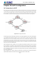
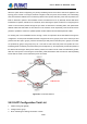
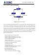
Table Of Contents
- Chapter 1 INTRODUCTION
- Chapter 2 INSTALLATION
- Chapter 3 Switch Management
- Chapter 4 Basic Switch Configuration
- Chapter 5 File System Operations
- Chapter 6 Cluster Configuration
- Chapter 7 Port Configuration
- Chapter 8 Port Isolation Function Configuration
- Chapter 9 Port Loopback Detection Function Configuration
- Chapter 10 ULDP Function Configuration
- Chapter 11 LLDP Function Operation Configuration
- Chapter 12 Port Channel Configuration
- Chapter 13 MTU Configuration
- Chapter 14 EFM OAM Configuration
- Chapter 15 PORT SECURITY
- Chapter 16 DDM Configuration
- Chapter 17 LLDP-MED
- Chapter 18 bpdu-tunnel Configuration
- Chapter 19 EEE Energy-saving Configuration
- Chapter 20 VLAN Configuration
- Chapter 21 MAC Table Configuration
- Chapter 22 MSTP Configuration
- Chapter 23 QoS Configuration
- Chapter 24 Flow-based Redirection
- Chapter 25 Flexible Q-in-Q Configuration
- Chapter 26 Layer 3 Management Configuration
- Chapter 27 ARP Scanning Prevention Function Configuration
- Chapter 28 Prevent ARP Spoofing Configuration
- Chapter 29 ARP GUARD Configuration
- Chapter 30 Gratuitous ARP Configuration
- Chapter 31 DHCP Configuration
- Chapter 32 DHCPv6 Configuration
- Chapter 33 DHCP Option 82 Configuration
- Chapter 34 DHCP Option 60 and option 43
- Chapter 35 DHCPv6 Options 37, 38
- Chapter 36 DHCP Snooping Configuration
- Chapter 37 DHCP Snooping Option 82 Configuration
- Chapter 38 IPv4 Multicast Protocol
- Chapter 39 IPv6 Multicast Protocol
- Chapter 40 Multicast VLAN
- Chapter 41 ACL Configuration
- Chapter 42 802.1x Configuration
- 42.1 Introduction to 802.1x
- 42.2 802.1x Configuration Task List
- 42.3 802.1x Application Example
- 42.4 802.1x Troubleshooting
- Chapter 43 The Number Limitation Function of MAC and IP in Port, VLAN Configuration
- Chapter 44 Operational Configuration of AM Function
- Chapter 45 Security Feature Configuration
- 45.1 Introduction to Security Feature
- 45.2 Security Feature Configuration
- 45.2.1 Prevent IP Spoofing Function Configuration Task Sequence
- 45.2.2 Prevent TCP Unauthorized Label Attack Function Configuration Task Sequence
- 45.2.3 Anti Port Cheat Function Configuration Task Sequence
- 45.2.4 Prevent TCP Fragment Attack Function Configuration Task Sequence
- 45.2.5 Prevent ICMP Fragment Attack Function Configuration Task Sequence
- 45.3 Security Feature Example
- Chapter 46 TACACS+ Configuration
- Chapter 47 RADIUS Configuration
- Chapter 48 SSL Configuration
- Chapter 49 IPv6 Security RA Configuration
- Chapter 50 MAB Configuration
- Chapter 51 PPPoE Intermediate Agent Configuration
- Chapter 52 Web Portal Configuration
- Chapter 53 VLAN-ACL Configuration
- Chapter 54 SAVI Configuration
- Chapter 55 MRPP Configuration
- Chapter 56 ULPP Configuration
- Chapter 57 ULSM Configuration
- Chapter 58 Mirror Configuration
- Chapter 59 sFlow Configuration
- Chapter 60 RSPAN Configuration
- Chapter 61 ERSPAN
- Chapter 62 SNTP Configuration
- Chapter 63 NTP Function Configuration
- Chapter 64 Summer Time Configuration
- Chapter 65 DNSv4/v6 Configuration
- Chapter 66 Monitor and Debug
- Chapter 67 Reload Switch after Specified Time
- Chapter 68 Debugging and Diagnosis for Packets Received and Sent by CPU
- Chapter 69 Dying Gasp Configuration
- Chapter 70 PoE Configuration

56-19
Chapter 56 ULPP Configuration
56.1 Introduction to ULPP
Each ULPP group has two uplink ports, they are master port and slave port. The port may be a physical port
or a port channel. The member ports of ULPP group have three states: Forwarding, Standby, Down. Normally,
only one port at the forwarding state, the other port is blocked at the Standby state. When the master port has
the link problem, the master port becomes down state, and the slave port is switched to forwarding state.
Figure 56-1: the using scene of ULPP
The above figure uses the double-uplink network, this is the typical application scene of ULPP. SwitchA goes
up to SwitchD through SwitchB and SwitchC, port A1 and port A2 are the uplink ports. SwitchA configures
ULPP and port A1 is set as the master port and port A2 is set as the slave port. When port A1 in the
forwarding state has the problem, switch the uplink at once and port A2 turns into the forwarding state. After
this, when recovering the master port, if the preemption mode is not configured, port A2 keeps the Forwarding
state, port A1 turns into the Standby state.
After the preemption mode is enabled, so as to the master port preempts the slave port when it recovered
from the problem. For avoiding the frequent uplink switch caused by the abnormity problem, the preemption
delay mechanism is imported, and it needs to wait for some times before the master port preempt the slave
port. For keeping the continuance of the flows, the master port does not process to preempt by default, but
turns into the Standby state.
When configuring ULPP, it needs to specify the VLAN which is protected by this ULPP group through the
method of MSTP instances, and ULPP does not provide the protection to other VLANs.
User’s Manual of SGS-6341 series