
SGS-6341-Series User Manual
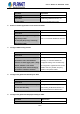
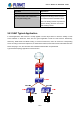
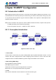
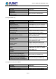
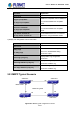
Table Of Contents
- Chapter 1 INTRODUCTION
- Chapter 2 INSTALLATION
- Chapter 3 Switch Management
- Chapter 4 Basic Switch Configuration
- Chapter 5 File System Operations
- Chapter 6 Cluster Configuration
- Chapter 7 Port Configuration
- Chapter 8 Port Isolation Function Configuration
- Chapter 9 Port Loopback Detection Function Configuration
- Chapter 10 ULDP Function Configuration
- Chapter 11 LLDP Function Operation Configuration
- Chapter 12 Port Channel Configuration
- Chapter 13 MTU Configuration
- Chapter 14 EFM OAM Configuration
- Chapter 15 PORT SECURITY
- Chapter 16 DDM Configuration
- Chapter 17 LLDP-MED
- Chapter 18 bpdu-tunnel Configuration
- Chapter 19 EEE Energy-saving Configuration
- Chapter 20 VLAN Configuration
- Chapter 21 MAC Table Configuration
- Chapter 22 MSTP Configuration
- Chapter 23 QoS Configuration
- Chapter 24 Flow-based Redirection
- Chapter 25 Flexible Q-in-Q Configuration
- Chapter 26 Layer 3 Management Configuration
- Chapter 27 ARP Scanning Prevention Function Configuration
- Chapter 28 Prevent ARP Spoofing Configuration
- Chapter 29 ARP GUARD Configuration
- Chapter 30 Gratuitous ARP Configuration
- Chapter 31 DHCP Configuration
- Chapter 32 DHCPv6 Configuration
- Chapter 33 DHCP Option 82 Configuration
- Chapter 34 DHCP Option 60 and option 43
- Chapter 35 DHCPv6 Options 37, 38
- Chapter 36 DHCP Snooping Configuration
- Chapter 37 DHCP Snooping Option 82 Configuration
- Chapter 38 IPv4 Multicast Protocol
- Chapter 39 IPv6 Multicast Protocol
- Chapter 40 Multicast VLAN
- Chapter 41 ACL Configuration
- Chapter 42 802.1x Configuration
- 42.1 Introduction to 802.1x
- 42.2 802.1x Configuration Task List
- 42.3 802.1x Application Example
- 42.4 802.1x Troubleshooting
- Chapter 43 The Number Limitation Function of MAC and IP in Port, VLAN Configuration
- Chapter 44 Operational Configuration of AM Function
- Chapter 45 Security Feature Configuration
- 45.1 Introduction to Security Feature
- 45.2 Security Feature Configuration
- 45.2.1 Prevent IP Spoofing Function Configuration Task Sequence
- 45.2.2 Prevent TCP Unauthorized Label Attack Function Configuration Task Sequence
- 45.2.3 Anti Port Cheat Function Configuration Task Sequence
- 45.2.4 Prevent TCP Fragment Attack Function Configuration Task Sequence
- 45.2.5 Prevent ICMP Fragment Attack Function Configuration Task Sequence
- 45.3 Security Feature Example
- Chapter 46 TACACS+ Configuration
- Chapter 47 RADIUS Configuration
- Chapter 48 SSL Configuration
- Chapter 49 IPv6 Security RA Configuration
- Chapter 50 MAB Configuration
- Chapter 51 PPPoE Intermediate Agent Configuration
- Chapter 52 Web Portal Configuration
- Chapter 53 VLAN-ACL Configuration
- Chapter 54 SAVI Configuration
- Chapter 55 MRPP Configuration
- Chapter 56 ULPP Configuration
- Chapter 57 ULSM Configuration
- Chapter 58 Mirror Configuration
- Chapter 59 sFlow Configuration
- Chapter 60 RSPAN Configuration
- Chapter 61 ERSPAN
- Chapter 62 SNTP Configuration
- Chapter 63 NTP Function Configuration
- Chapter 64 Summer Time Configuration
- Chapter 65 DNSv4/v6 Configuration
- Chapter 66 Monitor and Debug
- Chapter 67 Reload Switch after Specified Time
- Chapter 68 Debugging and Diagnosis for Packets Received and Sent by CPU
- Chapter 69 Dying Gasp Configuration
- Chapter 70 PoE Configuration

55-12
Primary node: each ring has a primary node, it is main node to detect and defend.
Transfer node: except for primary node, other nodes are transfer nodes on each ring.
The node role is determined by user configuration. As shown Figure 55-1, Switch A is primary node of Ring 1,
Switch B. Switch C; Switch D and Switch E are transfer nodes of Ring 1.
4. Primary port and secondary port
The primary node and transfer node have two ports connecting to Ethernet separately, one is primary port,
and another is secondary port. The role of port is determined by user configuration.
Primary port and secondary port of primary node.
The primary port of primary node is used to send ring health examine packet (hello), the secondary port is
used to receive Hello packet sending from primary node. When the Ethernet is in health state, the secondary
port of primary node blocks other data in logical and only MRPP packet can pass. When the Ethernet is in
break state, the secondary port of primary node releases block state, and forwards data packets.
There are no difference on function between Primary port and secondary port of transfer node.
The role of port is determined by user configuration. As shown in Figure 55-1, Switch A E1 is a primary port
while E2 is a secondary port.
5. Timer
The two timers are used when the primary node sends and receives MRPP protocol packet: Hello timer and
Fail Timer.
Hello timer: define timer of time interval of health examine packet sending by primary node primary port.
Fail timer: define timer of overtime interval of health examine packet receiving by primary node primary port.
The value of Fail timer must be more than or equal to the 3 times of value of Hello timer.
55.1.2 MRPP Protocol Packet Types
Packet Type Explanation
Hello packet (Health examine packet) Hello The primary port of primary node evokes to detect ring, if the
secondary port of primary node can receive Hello packet in
configured overtime, so the ring is normal.
LINK-DOWN (link Down event packet) After transfer node detects Down event on port, immediately
sends LINK-DOWN packet to primary node, and inform primary
node ring to fail.
LINK-DOWN-FLUSH_FDB packet After primary node detects ring failure or receives LINK-DOWN
packet, open blocked secondary port, and then uses two ports
to send the packet, to inform each transfer node to refresh own
MAC address.
User’s Manual of SGS-6341 series