
SGS-6341-Series User Manual
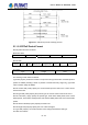
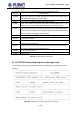
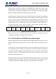
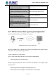

Table Of Contents
- Chapter 1 INTRODUCTION
- Chapter 2 INSTALLATION
- Chapter 3 Switch Management
- Chapter 4 Basic Switch Configuration
- Chapter 5 File System Operations
- Chapter 6 Cluster Configuration
- Chapter 7 Port Configuration
- Chapter 8 Port Isolation Function Configuration
- Chapter 9 Port Loopback Detection Function Configuration
- Chapter 10 ULDP Function Configuration
- Chapter 11 LLDP Function Operation Configuration
- Chapter 12 Port Channel Configuration
- Chapter 13 MTU Configuration
- Chapter 14 EFM OAM Configuration
- Chapter 15 PORT SECURITY
- Chapter 16 DDM Configuration
- Chapter 17 LLDP-MED
- Chapter 18 bpdu-tunnel Configuration
- Chapter 19 EEE Energy-saving Configuration
- Chapter 20 VLAN Configuration
- Chapter 21 MAC Table Configuration
- Chapter 22 MSTP Configuration
- Chapter 23 QoS Configuration
- Chapter 24 Flow-based Redirection
- Chapter 25 Flexible Q-in-Q Configuration
- Chapter 26 Layer 3 Management Configuration
- Chapter 27 ARP Scanning Prevention Function Configuration
- Chapter 28 Prevent ARP Spoofing Configuration
- Chapter 29 ARP GUARD Configuration
- Chapter 30 Gratuitous ARP Configuration
- Chapter 31 DHCP Configuration
- Chapter 32 DHCPv6 Configuration
- Chapter 33 DHCP Option 82 Configuration
- Chapter 34 DHCP Option 60 and option 43
- Chapter 35 DHCPv6 Options 37, 38
- Chapter 36 DHCP Snooping Configuration
- Chapter 37 DHCP Snooping Option 82 Configuration
- Chapter 38 IPv4 Multicast Protocol
- Chapter 39 IPv6 Multicast Protocol
- Chapter 40 Multicast VLAN
- Chapter 41 ACL Configuration
- Chapter 42 802.1x Configuration
- 42.1 Introduction to 802.1x
- 42.2 802.1x Configuration Task List
- 42.3 802.1x Application Example
- 42.4 802.1x Troubleshooting
- Chapter 43 The Number Limitation Function of MAC and IP in Port, VLAN Configuration
- Chapter 44 Operational Configuration of AM Function
- Chapter 45 Security Feature Configuration
- 45.1 Introduction to Security Feature
- 45.2 Security Feature Configuration
- 45.2.1 Prevent IP Spoofing Function Configuration Task Sequence
- 45.2.2 Prevent TCP Unauthorized Label Attack Function Configuration Task Sequence
- 45.2.3 Anti Port Cheat Function Configuration Task Sequence
- 45.2.4 Prevent TCP Fragment Attack Function Configuration Task Sequence
- 45.2.5 Prevent ICMP Fragment Attack Function Configuration Task Sequence
- 45.3 Security Feature Example
- Chapter 46 TACACS+ Configuration
- Chapter 47 RADIUS Configuration
- Chapter 48 SSL Configuration
- Chapter 49 IPv6 Security RA Configuration
- Chapter 50 MAB Configuration
- Chapter 51 PPPoE Intermediate Agent Configuration
- Chapter 52 Web Portal Configuration
- Chapter 53 VLAN-ACL Configuration
- Chapter 54 SAVI Configuration
- Chapter 55 MRPP Configuration
- Chapter 56 ULPP Configuration
- Chapter 57 ULSM Configuration
- Chapter 58 Mirror Configuration
- Chapter 59 sFlow Configuration
- Chapter 60 RSPAN Configuration
- Chapter 61 ERSPAN
- Chapter 62 SNTP Configuration
- Chapter 63 NTP Function Configuration
- Chapter 64 Summer Time Configuration
- Chapter 65 DNSv4/v6 Configuration
- Chapter 66 Monitor and Debug
- Chapter 67 Reload Switch after Specified Time
- Chapter 68 Debugging and Diagnosis for Packets Received and Sent by CPU
- Chapter 69 Dying Gasp Configuration
- Chapter 70 PoE Configuration

Add TL
V tag as 0x0105 for PPPoE IA, TA
G_LENGTH is length field of vendor tag;
0x00000DE9 is “ADSL Forum” IANA entry of the fixed 4 bytes; 0x01 is type field of Agent
Circuit ID, length is length field and Agent Circuit ID value field; 0x02 is type field of Agent
Remote ID, length is length field and Agent Remote ID value field.
PPPoE IA supplies a default circuit ID value, the default circuit ID (The figure in the following)
includes 5 fields, ANI (Access Node Identifier) can be configured by user, its length is less than
47 bytes. If there is no ANI configured, MAC is accessed by default, occupy 6 bytes and use
space symbol to compart, “eth” occupies 3 bytes and uses space symbol to compart, “Slot ID”
occupies 2 bytes, use “/” to compart and occupy 1 byte, “Port Index” occupies 3 bytes, use “:”
to compart and occupy 1 byte, “Vlan ID” occupies 4 bytes, all fields use ASCII, user can
configure circuit ID for each port according to requirement.
ANI
(n byte)
Space
( 1byte)
eth
(3 byte)
Space
(1 byte)
Slot ID
(2 byte)
/
(1byte)
Port Index
(3 byte)
:
(1 byte)
Vlan ID
(4 byte)
Figure 51-3: Agent Circuit ID value
MAC of the access switch is the default remote ID value of PPPoE IA. remote ID value can be
configured by user flexibly, the length is less than 63 bytes.
51.1.2.4 Trusted Port of PPPoE Intermediate Agent
Discovery stage sends five kinds of packets, PADI and PADR packets sent by client to server,
PADO and PADS packets sent by server to client, and PADT packet can be sent by server or
client.
In PPPoE IA, for security and reduced traffic, set a port connected server as trusted port, set
ports connected client as untrusted port, trusted port can receive all packets, untrusted port
can receive only PADI, PADR and PADT packets which are sent to server. To ensure client
operation is correct, it must set the port connecting to server as trusted port. Each access to
device has a trusted port at least.
PPPoE IA vendor tag can not exist in PPPoE packets sent by server to client, so we can strip
and forward these vendor tags if they exist in PPPoE packets. Strip function must be
configured on trusted port, enabling strip function not to take effect on untrusted port.
51-133
User’s Manual of SGS-6341 series