
SGS-6341-Series User Manual
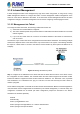
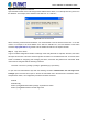
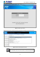
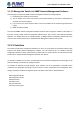
Table Of Contents
- Chapter 1 INTRODUCTION
- Chapter 2 INSTALLATION
- Chapter 3 Switch Management
- Chapter 4 Basic Switch Configuration
- Chapter 5 File System Operations
- Chapter 6 Cluster Configuration
- Chapter 7 Port Configuration
- Chapter 8 Port Isolation Function Configuration
- Chapter 9 Port Loopback Detection Function Configuration
- Chapter 10 ULDP Function Configuration
- Chapter 11 LLDP Function Operation Configuration
- Chapter 12 Port Channel Configuration
- Chapter 13 MTU Configuration
- Chapter 14 EFM OAM Configuration
- Chapter 15 PORT SECURITY
- Chapter 16 DDM Configuration
- Chapter 17 LLDP-MED
- Chapter 18 bpdu-tunnel Configuration
- Chapter 19 EEE Energy-saving Configuration
- Chapter 20 VLAN Configuration
- Chapter 21 MAC Table Configuration
- Chapter 22 MSTP Configuration
- Chapter 23 QoS Configuration
- Chapter 24 Flow-based Redirection
- Chapter 25 Flexible Q-in-Q Configuration
- Chapter 26 Layer 3 Management Configuration
- Chapter 27 ARP Scanning Prevention Function Configuration
- Chapter 28 Prevent ARP Spoofing Configuration
- Chapter 29 ARP GUARD Configuration
- Chapter 30 Gratuitous ARP Configuration
- Chapter 31 DHCP Configuration
- Chapter 32 DHCPv6 Configuration
- Chapter 33 DHCP Option 82 Configuration
- Chapter 34 DHCP Option 60 and option 43
- Chapter 35 DHCPv6 Options 37, 38
- Chapter 36 DHCP Snooping Configuration
- Chapter 37 DHCP Snooping Option 82 Configuration
- Chapter 38 IPv4 Multicast Protocol
- Chapter 39 IPv6 Multicast Protocol
- Chapter 40 Multicast VLAN
- Chapter 41 ACL Configuration
- Chapter 42 802.1x Configuration
- 42.1 Introduction to 802.1x
- 42.2 802.1x Configuration Task List
- 42.3 802.1x Application Example
- 42.4 802.1x Troubleshooting
- Chapter 43 The Number Limitation Function of MAC and IP in Port, VLAN Configuration
- Chapter 44 Operational Configuration of AM Function
- Chapter 45 Security Feature Configuration
- 45.1 Introduction to Security Feature
- 45.2 Security Feature Configuration
- 45.2.1 Prevent IP Spoofing Function Configuration Task Sequence
- 45.2.2 Prevent TCP Unauthorized Label Attack Function Configuration Task Sequence
- 45.2.3 Anti Port Cheat Function Configuration Task Sequence
- 45.2.4 Prevent TCP Fragment Attack Function Configuration Task Sequence
- 45.2.5 Prevent ICMP Fragment Attack Function Configuration Task Sequence
- 45.3 Security Feature Example
- Chapter 46 TACACS+ Configuration
- Chapter 47 RADIUS Configuration
- Chapter 48 SSL Configuration
- Chapter 49 IPv6 Security RA Configuration
- Chapter 50 MAB Configuration
- Chapter 51 PPPoE Intermediate Agent Configuration
- Chapter 52 Web Portal Configuration
- Chapter 53 VLAN-ACL Configuration
- Chapter 54 SAVI Configuration
- Chapter 55 MRPP Configuration
- Chapter 56 ULPP Configuration
- Chapter 57 ULSM Configuration
- Chapter 58 Mirror Configuration
- Chapter 59 sFlow Configuration
- Chapter 60 RSPAN Configuration
- Chapter 61 ERSPAN
- Chapter 62 SNTP Configuration
- Chapter 63 NTP Function Configuration
- Chapter 64 Summer Time Configuration
- Chapter 65 DNSv4/v6 Configuration
- Chapter 66 Monitor and Debug
- Chapter 67 Reload Switch after Specified Time
- Chapter 68 Debugging and Diagnosis for Packets Received and Sent by CPU
- Chapter 69 Dying Gasp Configuration
- Chapter 70 PoE Configuration

3.1.2 In-band Management
In-band management refers to the management by login to the switch using Telnet, or using HTTP, or using
SNMP management software to configure the switch. In-band management enables management of the
switch for some devices attached to the switch. In the case when in-band management fails due to switch
configuration changes, out-of-band management can be used for configuring and managing the switch.
3.1.2.1 Management via Telnet
To manage the switch with Telnet, the following conditions should be met:
1) Switch has an IPv4/IPv6 address configured;
2) The host IP address (Telnet client) and the switch’s VLAN interface IPv4/IPv6 address is in the same
network segment;
3) If 2) is not met, Telnet client can connect to an IPv4/IPv6 address of the switch via other devices,
such as a router.
The switch is Layer 3 switch that can be configured with several IPv4/IPv6 addresses. The following example
assumes the shipment status of the switch where only VLAN1 exists in the system. The following describes
the steps for a Telnet client to connect to the switch’s VLAN1 interface by Telnet (with IPv4 address as an
example):
Figure 3-6 Manage the Switch by Telnet
Step 1: Configure the IP addresses for the switch and start the Telnet Server function on the switch. First is
the configuration of host IP address. This should be within the same network segment as the switch VLAN1
interface IP address. Suppose the switch VLAN1 interface IP address is 10.1.128.251/24. Then, a possible
host IP address is 10.1.128.252/24. Run “ping 10.1.128.251” from the host and verify the result. Check for
reasons if ping fails.
The IP address configuration commands for VLAN1 interface are listed below. Before in-band management is
used, the switch must be configured with an IP address by out-of-band management (i.e. Console mode). The
configuration commands are as follows (All switch configuration prompts are assumed to be “Switch”
hereafter if not otherwise specified.):
Switch#
Switch#config
Switch (config)#interface vlan 1
Switch (Config-if-Vlan1)#ip address 10.1.128.251 255.255.255.0
Switch (Config-if-Vlan1)#no shutdown
3-5
User’s Manual of SGS-6341 series