
SGS-6341-Series User Manual
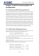
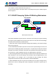
Table Of Contents
- Chapter 1 INTRODUCTION
- Chapter 2 INSTALLATION
- Chapter 3 Switch Management
- Chapter 4 Basic Switch Configuration
- Chapter 5 File System Operations
- Chapter 6 Cluster Configuration
- Chapter 7 Port Configuration
- Chapter 8 Port Isolation Function Configuration
- Chapter 9 Port Loopback Detection Function Configuration
- Chapter 10 ULDP Function Configuration
- Chapter 11 LLDP Function Operation Configuration
- Chapter 12 Port Channel Configuration
- Chapter 13 MTU Configuration
- Chapter 14 EFM OAM Configuration
- Chapter 15 PORT SECURITY
- Chapter 16 DDM Configuration
- Chapter 17 LLDP-MED
- Chapter 18 bpdu-tunnel Configuration
- Chapter 19 EEE Energy-saving Configuration
- Chapter 20 VLAN Configuration
- Chapter 21 MAC Table Configuration
- Chapter 22 MSTP Configuration
- Chapter 23 QoS Configuration
- Chapter 24 Flow-based Redirection
- Chapter 25 Flexible Q-in-Q Configuration
- Chapter 26 Layer 3 Management Configuration
- Chapter 27 ARP Scanning Prevention Function Configuration
- Chapter 28 Prevent ARP Spoofing Configuration
- Chapter 29 ARP GUARD Configuration
- Chapter 30 Gratuitous ARP Configuration
- Chapter 31 DHCP Configuration
- Chapter 32 DHCPv6 Configuration
- Chapter 33 DHCP Option 82 Configuration
- Chapter 34 DHCP Option 60 and option 43
- Chapter 35 DHCPv6 Options 37, 38
- Chapter 36 DHCP Snooping Configuration
- Chapter 37 DHCP Snooping Option 82 Configuration
- Chapter 38 IPv4 Multicast Protocol
- Chapter 39 IPv6 Multicast Protocol
- Chapter 40 Multicast VLAN
- Chapter 41 ACL Configuration
- Chapter 42 802.1x Configuration
- 42.1 Introduction to 802.1x
- 42.2 802.1x Configuration Task List
- 42.3 802.1x Application Example
- 42.4 802.1x Troubleshooting
- Chapter 43 The Number Limitation Function of MAC and IP in Port, VLAN Configuration
- Chapter 44 Operational Configuration of AM Function
- Chapter 45 Security Feature Configuration
- 45.1 Introduction to Security Feature
- 45.2 Security Feature Configuration
- 45.2.1 Prevent IP Spoofing Function Configuration Task Sequence
- 45.2.2 Prevent TCP Unauthorized Label Attack Function Configuration Task Sequence
- 45.2.3 Anti Port Cheat Function Configuration Task Sequence
- 45.2.4 Prevent TCP Fragment Attack Function Configuration Task Sequence
- 45.2.5 Prevent ICMP Fragment Attack Function Configuration Task Sequence
- 45.3 Security Feature Example
- Chapter 46 TACACS+ Configuration
- Chapter 47 RADIUS Configuration
- Chapter 48 SSL Configuration
- Chapter 49 IPv6 Security RA Configuration
- Chapter 50 MAB Configuration
- Chapter 51 PPPoE Intermediate Agent Configuration
- Chapter 52 Web Portal Configuration
- Chapter 53 VLAN-ACL Configuration
- Chapter 54 SAVI Configuration
- Chapter 55 MRPP Configuration
- Chapter 56 ULPP Configuration
- Chapter 57 ULSM Configuration
- Chapter 58 Mirror Configuration
- Chapter 59 sFlow Configuration
- Chapter 60 RSPAN Configuration
- Chapter 61 ERSPAN
- Chapter 62 SNTP Configuration
- Chapter 63 NTP Function Configuration
- Chapter 64 Summer Time Configuration
- Chapter 65 DNSv4/v6 Configuration
- Chapter 66 Monitor and Debug
- Chapter 67 Reload Switch after Specified Time
- Chapter 68 Debugging and Diagnosis for Packets Received and Sent by CPU
- Chapter 69 Dying Gasp Configuration
- Chapter 70 PoE Configuration

224.0.0.16 Specified SBM
224.0.0.17 All SBMS
224.0.0.18 VRRP
224.0.0.22 IGMP
When Ethernet transmits
Unicast IP messages, the destination MAC address it uses is the
receiver’s MAC address. But in transmitting Multicast packets, the transmission destination is
not a specific receiver any more, but a group with uncertain members, thus Multicast MAC
address is used. Multicast MAC address is corresponding to Multicast IP address. It is
prescribed in IANA (Internet Assigned Number Authority) that the higher 25 bits in Multicast
MAC address is 0x01005e, and the lower 23bits in MAC address is the lower 23bits in
Multicast IP address.
Since only 23bits out of the lower 28bits in IP Multicast address are mapped into MAC address,
therefore there are 32 IP Multicast addresses which are mapped into the same MAC address.
38.1.3 IP Multicast Packet Transmission
In Multicast mode, the source host sends packets to the host group indicated by the Multicast
group address in the destination address field of IP data packet. Unlike Unicast mode,
Multicast data packet must be forwarded to a number of external interfaces to be sent to all
receiver sites in Multicast mode, thus Multicast transmission procedure is more complicated
than Unicast transmission procedure.
In order to guarantee that all Multicast packets get to the router via the shortest path, the
receipt interface of the Multicast packet must be checked in some certain way based on
Unicast router table; this checking mechanism is the basis for most Multicast Routing Protocol
to forward in Multicast mode --- RPF (Reverse Path Forwarding) check. Multicast router makes
use of the impressed packet source address to query Unicast Router Table or independent
Multicast Router Table to determine if the packet ingress interface is on the shortest path from
receipt site to source address. If shortest path Tree is used, then the source address is the
address of source host which sends Multicast Data Packets; if Shared Tree is used, then the
source address is the address of the root of the Shared-Tree. When Multicast data packet gets
to the router, if RPF check passes, then the data packet is forwarded according to Multicast
forward item, and the data packet will be discarded else wise.
38.1.4 IP Multicast Application
IP Multicast technology has effectively solved the problem of sending in single point and
receiving in multipoint. It has achieved the effective data transmission from a point to multiple
points, saved a great deal of network bandwidth and reduced network load. Making use of the
Multicast property of network, some new value-added operations can be supplied conveniently.
38-27
User’s Manual of SGS-6341 series