
SGS-6341-Series User Manual
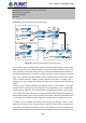
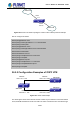
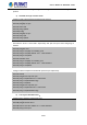
Table Of Contents
- Chapter 1 INTRODUCTION
- Chapter 2 INSTALLATION
- Chapter 3 Switch Management
- Chapter 4 Basic Switch Configuration
- Chapter 5 File System Operations
- Chapter 6 Cluster Configuration
- Chapter 7 Port Configuration
- Chapter 8 Port Isolation Function Configuration
- Chapter 9 Port Loopback Detection Function Configuration
- Chapter 10 ULDP Function Configuration
- Chapter 11 LLDP Function Operation Configuration
- Chapter 12 Port Channel Configuration
- Chapter 13 MTU Configuration
- Chapter 14 EFM OAM Configuration
- Chapter 15 PORT SECURITY
- Chapter 16 DDM Configuration
- Chapter 17 LLDP-MED
- Chapter 18 bpdu-tunnel Configuration
- Chapter 19 EEE Energy-saving Configuration
- Chapter 20 VLAN Configuration
- Chapter 21 MAC Table Configuration
- Chapter 22 MSTP Configuration
- Chapter 23 QoS Configuration
- Chapter 24 Flow-based Redirection
- Chapter 25 Flexible Q-in-Q Configuration
- Chapter 26 Layer 3 Management Configuration
- Chapter 27 ARP Scanning Prevention Function Configuration
- Chapter 28 Prevent ARP Spoofing Configuration
- Chapter 29 ARP GUARD Configuration
- Chapter 30 Gratuitous ARP Configuration
- Chapter 31 DHCP Configuration
- Chapter 32 DHCPv6 Configuration
- Chapter 33 DHCP Option 82 Configuration
- Chapter 34 DHCP Option 60 and option 43
- Chapter 35 DHCPv6 Options 37, 38
- Chapter 36 DHCP Snooping Configuration
- Chapter 37 DHCP Snooping Option 82 Configuration
- Chapter 38 IPv4 Multicast Protocol
- Chapter 39 IPv6 Multicast Protocol
- Chapter 40 Multicast VLAN
- Chapter 41 ACL Configuration
- Chapter 42 802.1x Configuration
- 42.1 Introduction to 802.1x
- 42.2 802.1x Configuration Task List
- 42.3 802.1x Application Example
- 42.4 802.1x Troubleshooting
- Chapter 43 The Number Limitation Function of MAC and IP in Port, VLAN Configuration
- Chapter 44 Operational Configuration of AM Function
- Chapter 45 Security Feature Configuration
- 45.1 Introduction to Security Feature
- 45.2 Security Feature Configuration
- 45.2.1 Prevent IP Spoofing Function Configuration Task Sequence
- 45.2.2 Prevent TCP Unauthorized Label Attack Function Configuration Task Sequence
- 45.2.3 Anti Port Cheat Function Configuration Task Sequence
- 45.2.4 Prevent TCP Fragment Attack Function Configuration Task Sequence
- 45.2.5 Prevent ICMP Fragment Attack Function Configuration Task Sequence
- 45.3 Security Feature Example
- Chapter 46 TACACS+ Configuration
- Chapter 47 RADIUS Configuration
- Chapter 48 SSL Configuration
- Chapter 49 IPv6 Security RA Configuration
- Chapter 50 MAB Configuration
- Chapter 51 PPPoE Intermediate Agent Configuration
- Chapter 52 Web Portal Configuration
- Chapter 53 VLAN-ACL Configuration
- Chapter 54 SAVI Configuration
- Chapter 55 MRPP Configuration
- Chapter 56 ULPP Configuration
- Chapter 57 ULSM Configuration
- Chapter 58 Mirror Configuration
- Chapter 59 sFlow Configuration
- Chapter 60 RSPAN Configuration
- Chapter 61 ERSPAN
- Chapter 62 SNTP Configuration
- Chapter 63 NTP Function Configuration
- Chapter 64 Summer Time Configuration
- Chapter 65 DNSv4/v6 Configuration
- Chapter 66 Monitor and Debug
- Chapter 67 Reload Switch after Specified Time
- Chapter 68 Debugging and Diagnosis for Packets Received and Sent by CPU
- Chapter 69 Dying Gasp Configuration
- Chapter 70 PoE Configuration

be a virtual link between backbone Layer 3 Switch10 and Switch
11. The area edge Layer 3
switches exchange summary information via the backbone Layer 3 switch, each area edge
Layer 3 switch listens to the summary information from the other edge Layer 3 switches.
Virtual link can not only maintain the connectivity of the backbone area, but also strengthen the
backbone area. For example, if the connection between backbone Layer 3 SwitchG and
Switch10 is cut down, the backbone area will become incontinuous. The backbone area can
become more robust by establishing a virtual link between backbone Layer 3 switches SwitchF
and Switch10. In addition, the virtual link between SwitchF and Switch10 provide a short path
from area 3 to Layer 3 Switch F.
Take area 1 as an example. Assume the IP address of Layer 3 SwitchA is 10.1.1.1, IP address
of Layer 3 Switch B interface VLAN2 is 10.1.1.2, IP address of Layer 3 SwitchC interface
VLAN2 is 10.1.1.3, IP address of Layer 3 SwitchD interface VLAN2 is 10.1.1.4. SwitchA is
connecting to network N1 through Ethernet interface VLAN1 (IP address 20.1.1.1); SwitchB is
connecting to network N2 through Ethernet interface VLAN1 (IP address 20.1.2.1); SwitchC is
connecting to network N4 through Ethernet interface VLAN3 (IP address 20.1.3.1). All the
three addresses belong to area 1. SwitchC is connecting to Layer 3 SwitchE through Ethernet
interface VLAN1 (IP address 10.1.5.1); SwitchD is connecting to Layer 3 SwitchD through
Ethernet interface VLAN1 (IP address 10.1.6.1); both two addresses belong to area 1. Simple
authentication is implemented among Layer 3 switches in area1, edge Layer 3 switches of
area 1 authenticate with the area 0 backbone Layer 3 switches by MD5 authentication.
The followings are just configurations for all Layer 3 switches in area 1, configurations for
Layer 3 switches of the other areas are omitted. The following are the configurations of
SwitchA, SwitchB, SwitchC and SwitchD:
1)Switch A:
Configure IP address for interface vlan2
SwitchA#config
SwitchA(config)# interface vlan 2
SwitchA(config-If-Vlan2)# ip address 10.1.1.1 255.255.255.0
SwitchA(config-If-Vlan2)#exit
Enable OSPF protocol, configure the area number for interface vlan2.
SwitchA(config)#router ospf
SwitchA(config-router)#network 10.1.1.0/24 area 1
SwitchA(config-router)#exit
Configure simple key authentication.
SwitchA(config)#interface vlan 2
SwitchA(config-If-Vlan2)#ip ospf authentication
26-38
User’s Manual of SGS-6341 series