
SGS-6341-Series User Manual
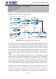
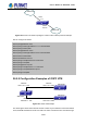
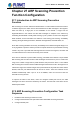
Table Of Contents
- Chapter 1 INTRODUCTION
- Chapter 2 INSTALLATION
- Chapter 3 Switch Management
- Chapter 4 Basic Switch Configuration
- Chapter 5 File System Operations
- Chapter 6 Cluster Configuration
- Chapter 7 Port Configuration
- Chapter 8 Port Isolation Function Configuration
- Chapter 9 Port Loopback Detection Function Configuration
- Chapter 10 ULDP Function Configuration
- Chapter 11 LLDP Function Operation Configuration
- Chapter 12 Port Channel Configuration
- Chapter 13 MTU Configuration
- Chapter 14 EFM OAM Configuration
- Chapter 15 PORT SECURITY
- Chapter 16 DDM Configuration
- Chapter 17 LLDP-MED
- Chapter 18 bpdu-tunnel Configuration
- Chapter 19 EEE Energy-saving Configuration
- Chapter 20 VLAN Configuration
- Chapter 21 MAC Table Configuration
- Chapter 22 MSTP Configuration
- Chapter 23 QoS Configuration
- Chapter 24 Flow-based Redirection
- Chapter 25 Flexible Q-in-Q Configuration
- Chapter 26 Layer 3 Management Configuration
- Chapter 27 ARP Scanning Prevention Function Configuration
- Chapter 28 Prevent ARP Spoofing Configuration
- Chapter 29 ARP GUARD Configuration
- Chapter 30 Gratuitous ARP Configuration
- Chapter 31 DHCP Configuration
- Chapter 32 DHCPv6 Configuration
- Chapter 33 DHCP Option 82 Configuration
- Chapter 34 DHCP Option 60 and option 43
- Chapter 35 DHCPv6 Options 37, 38
- Chapter 36 DHCP Snooping Configuration
- Chapter 37 DHCP Snooping Option 82 Configuration
- Chapter 38 IPv4 Multicast Protocol
- Chapter 39 IPv6 Multicast Protocol
- Chapter 40 Multicast VLAN
- Chapter 41 ACL Configuration
- Chapter 42 802.1x Configuration
- 42.1 Introduction to 802.1x
- 42.2 802.1x Configuration Task List
- 42.3 802.1x Application Example
- 42.4 802.1x Troubleshooting
- Chapter 43 The Number Limitation Function of MAC and IP in Port, VLAN Configuration
- Chapter 44 Operational Configuration of AM Function
- Chapter 45 Security Feature Configuration
- 45.1 Introduction to Security Feature
- 45.2 Security Feature Configuration
- 45.2.1 Prevent IP Spoofing Function Configuration Task Sequence
- 45.2.2 Prevent TCP Unauthorized Label Attack Function Configuration Task Sequence
- 45.2.3 Anti Port Cheat Function Configuration Task Sequence
- 45.2.4 Prevent TCP Fragment Attack Function Configuration Task Sequence
- 45.2.5 Prevent ICMP Fragment Attack Function Configuration Task Sequence
- 45.3 Security Feature Example
- Chapter 46 TACACS+ Configuration
- Chapter 47 RADIUS Configuration
- Chapter 48 SSL Configuration
- Chapter 49 IPv6 Security RA Configuration
- Chapter 50 MAB Configuration
- Chapter 51 PPPoE Intermediate Agent Configuration
- Chapter 52 Web Portal Configuration
- Chapter 53 VLAN-ACL Configuration
- Chapter 54 SAVI Configuration
- Chapter 55 MRPP Configuration
- Chapter 56 ULPP Configuration
- Chapter 57 ULSM Configuration
- Chapter 58 Mirror Configuration
- Chapter 59 sFlow Configuration
- Chapter 60 RSPAN Configuration
- Chapter 61 ERSPAN
- Chapter 62 SNTP Configuration
- Chapter 63 NTP Function Configuration
- Chapter 64 Summer Time Configuration
- Chapter 65 DNSv4/v6 Configuration
- Chapter 66 Monitor and Debug
- Chapter 67 Reload Switch after Specified Time
- Chapter 68 Debugging and Diagnosis for Packets Received and Sent by CPU
- Chapter 69 Dying Gasp Configuration
- Chapter 70 PoE Configuration

Switch5(config-router)# network 100.1.1.0/24 area 0
Switch5(config-router)#exit
Switch5(config)#exit
Switch5#
Scenario 2: Typical OSPF protocol complex topology.
Area 3
Area 2
Area 1
N3
N1
N8
N5
N6
N9
N10
N4
N2
N15 N14
N7
N11
Area 0
N12
N13
Switch H
Switch G
Switch J
Switch K
Switch L
Switch I
Switch F
Switch E
Switch D
Switch C
Switch B
Switch A
Figure 26-5 Typical
complex OSPF autonomous system
This scenario is a typical complex OSPF autonomous system network topology. Area1 include
network N1-N4 and Layer 3 SwitchA-SwitchD, area2 include network N8-N10, host H1 and
Layer 3 SwitchH, area3 include N5-N7 and Layer 3 SwitchF, SwitchG SwitchA0 and Switch11,
and network N8-N10 share a summary route with host H1(i.e. area3 is defined as a STUB
area). Layer 3 SwitchA, SwitchB, SwitchD, SwitchE, SwitchG, SwitchH, Switch12 are in-area
Layer 3 switches, SwitchC, SwitchD, SwitchF, Switch10 and Switch11 are edge Layer 3
switches of the area, SwitchD and SwitchF are edge Layer 3 switches of the autonomous
system.
To area1, Layer 3 switches SwitchA and SwitchB are both in-area switches, area edge
switches SwitchC and SwitchD are responsible for reporting distance cost to all destination
outside the area, while they are also responsible for reporting the position of the AS edge
Layer 3 switches SwitchD and SwitchF, AS exterior link-state advertisement from SwitchD and
SwitchF are flooded throughout the whole autonomous system. When ASE LSA floods in area
1, those LSAs are included in the area 1 database to get the routes to network N11 and N15.
In addition, Layer 3 SwitchC and SwitchD must summary the topology of area 1 to the
backbone area (area 0, all non-0 areas must be connected via area 0, direct connections are
not allowed), and advertise the networks in area 1 (N1-N4) and the costs from SwitchC and
SwitchD to those networks. As the backbone area is required to keep connected, there must
26-37
User’s Manual of SGS-6341 series