
SGS-6341-Series User Manual
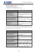
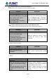
Table Of Contents
- Chapter 1 INTRODUCTION
- Chapter 2 INSTALLATION
- Chapter 3 Switch Management
- Chapter 4 Basic Switch Configuration
- Chapter 5 File System Operations
- Chapter 6 Cluster Configuration
- Chapter 7 Port Configuration
- Chapter 8 Port Isolation Function Configuration
- Chapter 9 Port Loopback Detection Function Configuration
- Chapter 10 ULDP Function Configuration
- Chapter 11 LLDP Function Operation Configuration
- Chapter 12 Port Channel Configuration
- Chapter 13 MTU Configuration
- Chapter 14 EFM OAM Configuration
- Chapter 15 PORT SECURITY
- Chapter 16 DDM Configuration
- Chapter 17 LLDP-MED
- Chapter 18 bpdu-tunnel Configuration
- Chapter 19 EEE Energy-saving Configuration
- Chapter 20 VLAN Configuration
- Chapter 21 MAC Table Configuration
- Chapter 22 MSTP Configuration
- Chapter 23 QoS Configuration
- Chapter 24 Flow-based Redirection
- Chapter 25 Flexible Q-in-Q Configuration
- Chapter 26 Layer 3 Management Configuration
- Chapter 27 ARP Scanning Prevention Function Configuration
- Chapter 28 Prevent ARP Spoofing Configuration
- Chapter 29 ARP GUARD Configuration
- Chapter 30 Gratuitous ARP Configuration
- Chapter 31 DHCP Configuration
- Chapter 32 DHCPv6 Configuration
- Chapter 33 DHCP Option 82 Configuration
- Chapter 34 DHCP Option 60 and option 43
- Chapter 35 DHCPv6 Options 37, 38
- Chapter 36 DHCP Snooping Configuration
- Chapter 37 DHCP Snooping Option 82 Configuration
- Chapter 38 IPv4 Multicast Protocol
- Chapter 39 IPv6 Multicast Protocol
- Chapter 40 Multicast VLAN
- Chapter 41 ACL Configuration
- Chapter 42 802.1x Configuration
- 42.1 Introduction to 802.1x
- 42.2 802.1x Configuration Task List
- 42.3 802.1x Application Example
- 42.4 802.1x Troubleshooting
- Chapter 43 The Number Limitation Function of MAC and IP in Port, VLAN Configuration
- Chapter 44 Operational Configuration of AM Function
- Chapter 45 Security Feature Configuration
- 45.1 Introduction to Security Feature
- 45.2 Security Feature Configuration
- 45.2.1 Prevent IP Spoofing Function Configuration Task Sequence
- 45.2.2 Prevent TCP Unauthorized Label Attack Function Configuration Task Sequence
- 45.2.3 Anti Port Cheat Function Configuration Task Sequence
- 45.2.4 Prevent TCP Fragment Attack Function Configuration Task Sequence
- 45.2.5 Prevent ICMP Fragment Attack Function Configuration Task Sequence
- 45.3 Security Feature Example
- Chapter 46 TACACS+ Configuration
- Chapter 47 RADIUS Configuration
- Chapter 48 SSL Configuration
- Chapter 49 IPv6 Security RA Configuration
- Chapter 50 MAB Configuration
- Chapter 51 PPPoE Intermediate Agent Configuration
- Chapter 52 Web Portal Configuration
- Chapter 53 VLAN-ACL Configuration
- Chapter 54 SAVI Configuration
- Chapter 55 MRPP Configuration
- Chapter 56 ULPP Configuration
- Chapter 57 ULSM Configuration
- Chapter 58 Mirror Configuration
- Chapter 59 sFlow Configuration
- Chapter 60 RSPAN Configuration
- Chapter 61 ERSPAN
- Chapter 62 SNTP Configuration
- Chapter 63 NTP Function Configuration
- Chapter 64 Summer Time Configuration
- Chapter 65 DNSv4/v6 Configuration
- Chapter 66 Monitor and Debug
- Chapter 67 Reload Switch after Specified Time
- Chapter 68 Debugging and Diagnosis for Packets Received and Sent by CPU
- Chapter 69 Dying Gasp Configuration
- Chapter 70 PoE Configuration

summary LSA) and type5 LSA (AS external LSA
) are not allowed to flood into/through STUB
areas. STUB areas must use the default routes, the Layer 3 switches on STUB area edge
advertise the default routes to STUB areas by type 3 summary LSA, those default routes only
floods inside STUB area and will not get out of STUB area. Each STUB area has a
corresponding default route, the route from a STUB area to AS exterior destination must rely
on the default route of that area.
The following simply outlines the route calculation process of OSPF protocol:
1) Each OSPF-enabled Layer 3 switch maintains a database (LS database) describing
the link-state of the topology structure of the whole autonomous system. Each Layer
3 switch generates a link-state advertisement according to its surrounding network
topology structure (router LSA), and sends the LSA to other Layer 3 switches through
link-state update (LSU) packets. Thus each Layer 3 switches receives LSAs from
other Layer 3 switches, and all LSAs are combined to the link-state database.
2) Since a LSA is the description of the network topology structure around a Layer 3
switch, the LS database is the description of the network topology structure of the
whole network. The Layer 3 switches can easily create a weighted vector map
according to the LS database. Obviously, all Layer 3 switches in the same
autonomous system will have the same network topology map.
3) Each Layer 3 switch uses the shortest path first (SPF) algorithm to calculate a tree of
shortest path rooted by itself. The tree provides the route to all the nodes in the
autonomous system, leaf nodes consist of the exterior route information. The exterior
route can be marked by the Layer 3 switch broadcast it, so that additional information
about the autonomous system can be recorded. As a result, the route table of each
Layer 3 switch is different.
OSPF protocol is developed by the IETF, the OSPF v2 widely used now is fulfilled according to
the content described in RFC2328.
26.5.2 OSPF Configuration Task List
The OSPF configuration for SGS-6341 Series switches may be different from the configuration
procedure to switches of the other manufacturers. It is a two-step process:
Enable OSPF in the Global Mode;2, Configure OSPF area for the interfaces. The configuration
task list is as follows:
1. Enable OSPF protocol (required)
(1) Enable/disable OSPF protocol (required)
(2) Configure the ID number of the Layer 3 switch running OSPF (optional)
(3) Configure the network scope for running OSPF (optional)
(4) Configure the area for the interface (required)
2. Configure OSPF protocol parameters (optional)
(1) Configure OSPF packet sending mechanism parameters
1) Configure OSPF packet verification
26-29
User’s Manual of SGS-6341 series