
SGS-6341-Series User Manual
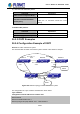
Table Of Contents
- Chapter 1 INTRODUCTION
- Chapter 2 INSTALLATION
- Chapter 3 Switch Management
- Chapter 4 Basic Switch Configuration
- Chapter 5 File System Operations
- Chapter 6 Cluster Configuration
- Chapter 7 Port Configuration
- Chapter 8 Port Isolation Function Configuration
- Chapter 9 Port Loopback Detection Function Configuration
- Chapter 10 ULDP Function Configuration
- Chapter 11 LLDP Function Operation Configuration
- Chapter 12 Port Channel Configuration
- Chapter 13 MTU Configuration
- Chapter 14 EFM OAM Configuration
- Chapter 15 PORT SECURITY
- Chapter 16 DDM Configuration
- Chapter 17 LLDP-MED
- Chapter 18 bpdu-tunnel Configuration
- Chapter 19 EEE Energy-saving Configuration
- Chapter 20 VLAN Configuration
- Chapter 21 MAC Table Configuration
- Chapter 22 MSTP Configuration
- Chapter 23 QoS Configuration
- Chapter 24 Flow-based Redirection
- Chapter 25 Flexible Q-in-Q Configuration
- Chapter 26 Layer 3 Management Configuration
- Chapter 27 ARP Scanning Prevention Function Configuration
- Chapter 28 Prevent ARP Spoofing Configuration
- Chapter 29 ARP GUARD Configuration
- Chapter 30 Gratuitous ARP Configuration
- Chapter 31 DHCP Configuration
- Chapter 32 DHCPv6 Configuration
- Chapter 33 DHCP Option 82 Configuration
- Chapter 34 DHCP Option 60 and option 43
- Chapter 35 DHCPv6 Options 37, 38
- Chapter 36 DHCP Snooping Configuration
- Chapter 37 DHCP Snooping Option 82 Configuration
- Chapter 38 IPv4 Multicast Protocol
- Chapter 39 IPv6 Multicast Protocol
- Chapter 40 Multicast VLAN
- Chapter 41 ACL Configuration
- Chapter 42 802.1x Configuration
- 42.1 Introduction to 802.1x
- 42.2 802.1x Configuration Task List
- 42.3 802.1x Application Example
- 42.4 802.1x Troubleshooting
- Chapter 43 The Number Limitation Function of MAC and IP in Port, VLAN Configuration
- Chapter 44 Operational Configuration of AM Function
- Chapter 45 Security Feature Configuration
- 45.1 Introduction to Security Feature
- 45.2 Security Feature Configuration
- 45.2.1 Prevent IP Spoofing Function Configuration Task Sequence
- 45.2.2 Prevent TCP Unauthorized Label Attack Function Configuration Task Sequence
- 45.2.3 Anti Port Cheat Function Configuration Task Sequence
- 45.2.4 Prevent TCP Fragment Attack Function Configuration Task Sequence
- 45.2.5 Prevent ICMP Fragment Attack Function Configuration Task Sequence
- 45.3 Security Feature Example
- Chapter 46 TACACS+ Configuration
- Chapter 47 RADIUS Configuration
- Chapter 48 SSL Configuration
- Chapter 49 IPv6 Security RA Configuration
- Chapter 50 MAB Configuration
- Chapter 51 PPPoE Intermediate Agent Configuration
- Chapter 52 Web Portal Configuration
- Chapter 53 VLAN-ACL Configuration
- Chapter 54 SAVI Configuration
- Chapter 55 MRPP Configuration
- Chapter 56 ULPP Configuration
- Chapter 57 ULSM Configuration
- Chapter 58 Mirror Configuration
- Chapter 59 sFlow Configuration
- Chapter 60 RSPAN Configuration
- Chapter 61 ERSPAN
- Chapter 62 SNTP Configuration
- Chapter 63 NTP Function Configuration
- Chapter 64 Summer Time Configuration
- Chapter 65 DNSv4/v6 Configuration
- Chapter 66 Monitor and Debug
- Chapter 67 Reload Switch after Specified Time
- Chapter 68 Debugging and Diagnosis for Packets Received and Sent by CPU
- Chapter 69 Dying Gasp Configuration
- Chapter 70 PoE Configuration

link-state information) to exchange link-st
ate information with other OSPF Layer 3 switches to
form a link-state database describing the whole autonomous system. Each Layer 3 switch
builds a shortest path tree rooted by itself according to the link-state database, this tree
provides the routes to all nodes in an autonomous system. If two or more Layer 3 switches
exist (i.e. multi-access network), "designated Layer 3 switch” and “backup designated Layer 3
switch” will be selected. Designated Layer 3 switch is responsible for spreading link-state of
the network. This concept helps reducing the traffic among the Layer 3 switches in
multi-access network.
OSPF protocol requires the autonomous system to be divided into areas. That is to divide the
autonomous system into 0 area (backbone area) and non-0 areas. Routing information
between areas are further abstracted and summarized to reduce the bandwidth required in the
network. OSPF uses four different kinds of routes; they are intra-area route, inter-area route,
type 1 external route and type 2 external route, in the order of highest priority to lowest. The
route inside an area and between areas describes the internal network structure of an
autonomous system, while external routes describe how to select the routing information to
destination outside the autonomous system. The first type of exterior route corresponds to the
information introduced by OSPF from the other interior routing protocols, the costs of those
routes are comparable with the costs of OSPF routes; the second type of exterior route
corresponds to the information introduced by OSPF from the other exterior routing protocols,
but the costs of those routes are far greater than that of OSPF routes, so OSPF route cost is
ignored when calculating route costs.
OSPF areas are centered with the Backbone area, identified as Area 0, all the other areas
must be connected to Area 0 logically, and Area 0 must be continuous. For this reason, the
concept of virtual link is introduced to the backbone area, so that physically separated areas
still have logical connectivity to the backbone area. The configurations of all the Layer 3
switches in the same area must be the same.
In conclusion, LSA can only be transferred between neighboring Layer 3 switches, OSPF
protocol includes 5 types of LSA: router LSA, network LSA, network summary LSA to the other
areas, ASBR summary LSA and AS external LSA. They can also be called type1 LSA, type2
LSA, type3 LSA, type4 LSA, and type5 LSA. Router LSA is generated by each Layer 3 switch
inside an OSPF area, and is sent to all the other neighboring Layer 3 switches in the same
area; network LSA is generated by the designated Layer 3 switch in the OSPF area of
multi-access network, and is sent to all other neighboring Layer 3 switches in this area. (In
order to reduce traffic on Layer 3 switches in the multi-access network, “designated Layer 3
switch” and “backup designated Layer 3 switch” should be selected in the multi-access
network, and the network link-state is broadcasted by the designated Layer 3 switch); network
summary LSA is generated by border switches in an OSPF area , and is transferred among
area border Layer 3 switches; AS external LSA is generated by Layer 3 switches on external
border of AS, and is transferred throughout the AS.
As to autonomous systems mainly advertises exterior link-state, OSPF allow some areas to be
configured as STUB areas to reduce the size of the topology database. Type4 LSA (ASBR
26-28
User’s Manual of SGS-6341 series