
SGS-6341-Series User Manual
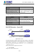
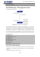
Table Of Contents
- Chapter 1 INTRODUCTION
- Chapter 2 INSTALLATION
- Chapter 3 Switch Management
- Chapter 4 Basic Switch Configuration
- Chapter 5 File System Operations
- Chapter 6 Cluster Configuration
- Chapter 7 Port Configuration
- Chapter 8 Port Isolation Function Configuration
- Chapter 9 Port Loopback Detection Function Configuration
- Chapter 10 ULDP Function Configuration
- Chapter 11 LLDP Function Operation Configuration
- Chapter 12 Port Channel Configuration
- Chapter 13 MTU Configuration
- Chapter 14 EFM OAM Configuration
- Chapter 15 PORT SECURITY
- Chapter 16 DDM Configuration
- Chapter 17 LLDP-MED
- Chapter 18 bpdu-tunnel Configuration
- Chapter 19 EEE Energy-saving Configuration
- Chapter 20 VLAN Configuration
- Chapter 21 MAC Table Configuration
- Chapter 22 MSTP Configuration
- Chapter 23 QoS Configuration
- Chapter 24 Flow-based Redirection
- Chapter 25 Flexible Q-in-Q Configuration
- Chapter 26 Layer 3 Management Configuration
- Chapter 27 ARP Scanning Prevention Function Configuration
- Chapter 28 Prevent ARP Spoofing Configuration
- Chapter 29 ARP GUARD Configuration
- Chapter 30 Gratuitous ARP Configuration
- Chapter 31 DHCP Configuration
- Chapter 32 DHCPv6 Configuration
- Chapter 33 DHCP Option 82 Configuration
- Chapter 34 DHCP Option 60 and option 43
- Chapter 35 DHCPv6 Options 37, 38
- Chapter 36 DHCP Snooping Configuration
- Chapter 37 DHCP Snooping Option 82 Configuration
- Chapter 38 IPv4 Multicast Protocol
- Chapter 39 IPv6 Multicast Protocol
- Chapter 40 Multicast VLAN
- Chapter 41 ACL Configuration
- Chapter 42 802.1x Configuration
- 42.1 Introduction to 802.1x
- 42.2 802.1x Configuration Task List
- 42.3 802.1x Application Example
- 42.4 802.1x Troubleshooting
- Chapter 43 The Number Limitation Function of MAC and IP in Port, VLAN Configuration
- Chapter 44 Operational Configuration of AM Function
- Chapter 45 Security Feature Configuration
- 45.1 Introduction to Security Feature
- 45.2 Security Feature Configuration
- 45.2.1 Prevent IP Spoofing Function Configuration Task Sequence
- 45.2.2 Prevent TCP Unauthorized Label Attack Function Configuration Task Sequence
- 45.2.3 Anti Port Cheat Function Configuration Task Sequence
- 45.2.4 Prevent TCP Fragment Attack Function Configuration Task Sequence
- 45.2.5 Prevent ICMP Fragment Attack Function Configuration Task Sequence
- 45.3 Security Feature Example
- Chapter 46 TACACS+ Configuration
- Chapter 47 RADIUS Configuration
- Chapter 48 SSL Configuration
- Chapter 49 IPv6 Security RA Configuration
- Chapter 50 MAB Configuration
- Chapter 51 PPPoE Intermediate Agent Configuration
- Chapter 52 Web Portal Configuration
- Chapter 53 VLAN-ACL Configuration
- Chapter 54 SAVI Configuration
- Chapter 55 MRPP Configuration
- Chapter 56 ULPP Configuration
- Chapter 57 ULSM Configuration
- Chapter 58 Mirror Configuration
- Chapter 59 sFlow Configuration
- Chapter 60 RSPAN Configuration
- Chapter 61 ERSPAN
- Chapter 62 SNTP Configuration
- Chapter 63 NTP Function Configuration
- Chapter 64 Summer Time Configuration
- Chapter 65 DNSv4/v6 Configuration
- Chapter 66 Monitor and Debug
- Chapter 67 Reload Switch after Specified Time
- Chapter 68 Debugging and Diagnosis for Packets Received and Sent by CPU
- Chapter 69 Dying Gasp Configuration
- Chapter 70 PoE Configuration

Second, ensure the interface and chain protoco
l are UP (use show interface
command)
Then initiate the RIP protocol (use router rip command) and configure the segment
(use network command) and set RIP protocol parameter on corresponding interfaces,
such as the option between RIP-I and RIP-II
After that, one feature of RIP protocol should be noticed ---the Layer 3 switch running
RIP protocol sending route updating messages to all neighboring Layer 3 switches
every 30 seconds. A Layer 3 switch is considered inaccessible if no route updating
messages from the switch is received within 180 seconds, then the route to the switch
will remains in the route table for 120 seconds before it is deleted. Therefore, if to delete
a RIP route, this route item is assured to be deleted from route table after 300 seconds.
When exchanging routing messages with CE using RIP protocol on the PE router, we
should first create corresponding VPN routing/transmitting examples to associate with
corresponding interfaces. Then enter the RIP address family mode configuring
corresponding parameters. If the RIP routing problem remains unresolved, please use
debug rip command to record the debug message in three minutes, and send them to
our technical service center.
26.5 OSPF
26.5.1 Introduction to OSPF
OSPF is abbreviation for Open Shortest Path First. It is an interior dynamic routing protocol for
autonomous system based on link-state. The protocol creates a link-state database by
exchanging link-states among Layer 3 switches, and then uses the Shortest Path First
algorithm to generate a route table basing on that database.
Autonomous system (AS) is a self-managed interconnected network. In large networks, such
as the Internet, a giant interconnected network is broken down to autonomous systems. Big
enterprise networks connecting to the Internet are independent AS, since the other hosts on
the Internet are not managed by those AS and they don’t share interior routing information with
the Layer 3 switches on the Internet.
Each link-state Layer 3 switch can provide information about the topology with its neighboring
Layer 3 switches.
• The network segment (link) connecting to the Layer 3 switch
• State of the connecting link
Link-state information is flooded throughout the network so that all Layer 3 switches can get
firsthand information. Link-state Layer 3 switches will not broadcast all information contained in
their route tables; instead, they only send changed link-state information. Link-state Layer 3
switches establish neighborhood by sending “HELLO” to their neighbors, then link-state
advertisements (LSA) will be sent among neighboring Layer 3 switches. Neighboring Layer 3
switch copy the LSA to their routing table and transfer the information to the rest part of the
26-26
User’s Manual of SGS-6341 series