
SGS-6341-Series User Manual
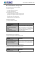
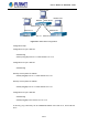
Table Of Contents
- Chapter 1 INTRODUCTION
- Chapter 2 INSTALLATION
- Chapter 3 Switch Management
- Chapter 4 Basic Switch Configuration
- Chapter 5 File System Operations
- Chapter 6 Cluster Configuration
- Chapter 7 Port Configuration
- Chapter 8 Port Isolation Function Configuration
- Chapter 9 Port Loopback Detection Function Configuration
- Chapter 10 ULDP Function Configuration
- Chapter 11 LLDP Function Operation Configuration
- Chapter 12 Port Channel Configuration
- Chapter 13 MTU Configuration
- Chapter 14 EFM OAM Configuration
- Chapter 15 PORT SECURITY
- Chapter 16 DDM Configuration
- Chapter 17 LLDP-MED
- Chapter 18 bpdu-tunnel Configuration
- Chapter 19 EEE Energy-saving Configuration
- Chapter 20 VLAN Configuration
- Chapter 21 MAC Table Configuration
- Chapter 22 MSTP Configuration
- Chapter 23 QoS Configuration
- Chapter 24 Flow-based Redirection
- Chapter 25 Flexible Q-in-Q Configuration
- Chapter 26 Layer 3 Management Configuration
- Chapter 27 ARP Scanning Prevention Function Configuration
- Chapter 28 Prevent ARP Spoofing Configuration
- Chapter 29 ARP GUARD Configuration
- Chapter 30 Gratuitous ARP Configuration
- Chapter 31 DHCP Configuration
- Chapter 32 DHCPv6 Configuration
- Chapter 33 DHCP Option 82 Configuration
- Chapter 34 DHCP Option 60 and option 43
- Chapter 35 DHCPv6 Options 37, 38
- Chapter 36 DHCP Snooping Configuration
- Chapter 37 DHCP Snooping Option 82 Configuration
- Chapter 38 IPv4 Multicast Protocol
- Chapter 39 IPv6 Multicast Protocol
- Chapter 40 Multicast VLAN
- Chapter 41 ACL Configuration
- Chapter 42 802.1x Configuration
- 42.1 Introduction to 802.1x
- 42.2 802.1x Configuration Task List
- 42.3 802.1x Application Example
- 42.4 802.1x Troubleshooting
- Chapter 43 The Number Limitation Function of MAC and IP in Port, VLAN Configuration
- Chapter 44 Operational Configuration of AM Function
- Chapter 45 Security Feature Configuration
- 45.1 Introduction to Security Feature
- 45.2 Security Feature Configuration
- 45.2.1 Prevent IP Spoofing Function Configuration Task Sequence
- 45.2.2 Prevent TCP Unauthorized Label Attack Function Configuration Task Sequence
- 45.2.3 Anti Port Cheat Function Configuration Task Sequence
- 45.2.4 Prevent TCP Fragment Attack Function Configuration Task Sequence
- 45.2.5 Prevent ICMP Fragment Attack Function Configuration Task Sequence
- 45.3 Security Feature Example
- Chapter 46 TACACS+ Configuration
- Chapter 47 RADIUS Configuration
- Chapter 48 SSL Configuration
- Chapter 49 IPv6 Security RA Configuration
- Chapter 50 MAB Configuration
- Chapter 51 PPPoE Intermediate Agent Configuration
- Chapter 52 Web Portal Configuration
- Chapter 53 VLAN-ACL Configuration
- Chapter 54 SAVI Configuration
- Chapter 55 MRPP Configuration
- Chapter 56 ULPP Configuration
- Chapter 57 ULSM Configuration
- Chapter 58 Mirror Configuration
- Chapter 59 sFlow Configuration
- Chapter 60 RSPAN Configuration
- Chapter 61 ERSPAN
- Chapter 62 SNTP Configuration
- Chapter 63 NTP Function Configuration
- Chapter 64 Summer Time Configuration
- Chapter 65 DNSv4/v6 Configuration
- Chapter 66 Monitor and Debug
- Chapter 67 Reload Switch after Specified Time
- Chapter 68 Debugging and Diagnosis for Packets Received and Sent by CPU
- Chapter 69 Dying Gasp Configuration
- Chapter 70 PoE Configuration

packets by packet
s broadcast, subnet mask and authentication is not supported. Some fields
in the RIP-I packets are not used and are required to be all 0’s; for this reason, such all 0's
fields should be checked when using RIP-I, the RIP-I packets should be discarded if such
fields are non-zero. RIP-II is a more improved version than RIP-I. RIP-II sends route update
packets by multicast packets (multicast address is 224.0.0.9). Subnet mask field and RIP
authentication filed (simple plaintext password and MD5 password authentication are
supported), and support variable length subnet mask. RIP-II used some of the zero field of
RIP-I and require no zero field verification. Switch sends RIP-II packets in multicast by default,
both RIP-I and RIP-II packets will be accepted.
Each Layer 3 switch running RIP has a route database, which contains all route entries for
reachable destination, and route table is built based on this database. When a RIP Layer 3
switch sent route update packets to its neighbor devices, the complete route table is included
in the packets. Therefore, in a large network, routing data to be transferred and processed for
each Layer 3 switch is quite large, causing degraded network performance.
Besides the above mentioned, RIP protocol allows route information discovered by the other
routing protocols to be introduced to the route table.
The operation of RIP protocol is shown below:
1. Enable RIP. The switch sends request packets to the neighbor Layer 3 switches
by broadcasting; on receiving the request, the neighbor devices reply with the
packets containing their local routing information.
2. The Layer 3 switch modifies its local route table on receiving the reply packets
and sends triggered update packets to the neighbor devices to advertise route
update information. On receiving the triggered update packet, the neighbor lay3
switches send triggered update packets to their neighbor lay3 switches. After a
sequence of triggered update packet broadcast, all Layer 3 switches get and
maintain the latest route information.
In addition, RIP Layer 3 switches will advertise its local route table to their neighbor devices
every 30 seconds. On receiving the packets, neighbor devices maintain their local route table,
select the best route and advertise the updated information to their own neighbor devices, so
that the updated routes are globally valid. Moreover, RIP uses a timeout mechanism for
outdated route, that is, if a switch does not receive regular update packets from a neighbor
within a certain interval (invalid timer interval), it considers the route from that neighbor invalid,
after holding the route fro a certain interval (holddown timer interval), it will delete that route.
26.4.2 RIP Configuration Task List
1. Enable RIP (required)
(1) Enable/disable RIP module.
(2) Enable interface to send/receive RIP packets
26-16
User’s Manual of SGS-6341 series