
SGS-6341-Series User Manual
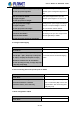
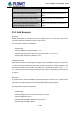

Table Of Contents
- Chapter 1 INTRODUCTION
- Chapter 2 INSTALLATION
- Chapter 3 Switch Management
- Chapter 4 Basic Switch Configuration
- Chapter 5 File System Operations
- Chapter 6 Cluster Configuration
- Chapter 7 Port Configuration
- Chapter 8 Port Isolation Function Configuration
- Chapter 9 Port Loopback Detection Function Configuration
- Chapter 10 ULDP Function Configuration
- Chapter 11 LLDP Function Operation Configuration
- Chapter 12 Port Channel Configuration
- Chapter 13 MTU Configuration
- Chapter 14 EFM OAM Configuration
- Chapter 15 PORT SECURITY
- Chapter 16 DDM Configuration
- Chapter 17 LLDP-MED
- Chapter 18 bpdu-tunnel Configuration
- Chapter 19 EEE Energy-saving Configuration
- Chapter 20 VLAN Configuration
- Chapter 21 MAC Table Configuration
- Chapter 22 MSTP Configuration
- Chapter 23 QoS Configuration
- Chapter 24 Flow-based Redirection
- Chapter 25 Flexible Q-in-Q Configuration
- Chapter 26 Layer 3 Management Configuration
- Chapter 27 ARP Scanning Prevention Function Configuration
- Chapter 28 Prevent ARP Spoofing Configuration
- Chapter 29 ARP GUARD Configuration
- Chapter 30 Gratuitous ARP Configuration
- Chapter 31 DHCP Configuration
- Chapter 32 DHCPv6 Configuration
- Chapter 33 DHCP Option 82 Configuration
- Chapter 34 DHCP Option 60 and option 43
- Chapter 35 DHCPv6 Options 37, 38
- Chapter 36 DHCP Snooping Configuration
- Chapter 37 DHCP Snooping Option 82 Configuration
- Chapter 38 IPv4 Multicast Protocol
- Chapter 39 IPv6 Multicast Protocol
- Chapter 40 Multicast VLAN
- Chapter 41 ACL Configuration
- Chapter 42 802.1x Configuration
- 42.1 Introduction to 802.1x
- 42.2 802.1x Configuration Task List
- 42.3 802.1x Application Example
- 42.4 802.1x Troubleshooting
- Chapter 43 The Number Limitation Function of MAC and IP in Port, VLAN Configuration
- Chapter 44 Operational Configuration of AM Function
- Chapter 45 Security Feature Configuration
- 45.1 Introduction to Security Feature
- 45.2 Security Feature Configuration
- 45.2.1 Prevent IP Spoofing Function Configuration Task Sequence
- 45.2.2 Prevent TCP Unauthorized Label Attack Function Configuration Task Sequence
- 45.2.3 Anti Port Cheat Function Configuration Task Sequence
- 45.2.4 Prevent TCP Fragment Attack Function Configuration Task Sequence
- 45.2.5 Prevent ICMP Fragment Attack Function Configuration Task Sequence
- 45.3 Security Feature Example
- Chapter 46 TACACS+ Configuration
- Chapter 47 RADIUS Configuration
- Chapter 48 SSL Configuration
- Chapter 49 IPv6 Security RA Configuration
- Chapter 50 MAB Configuration
- Chapter 51 PPPoE Intermediate Agent Configuration
- Chapter 52 Web Portal Configuration
- Chapter 53 VLAN-ACL Configuration
- Chapter 54 SAVI Configuration
- Chapter 55 MRPP Configuration
- Chapter 56 ULPP Configuration
- Chapter 57 ULSM Configuration
- Chapter 58 Mirror Configuration
- Chapter 59 sFlow Configuration
- Chapter 60 RSPAN Configuration
- Chapter 61 ERSPAN
- Chapter 62 SNTP Configuration
- Chapter 63 NTP Function Configuration
- Chapter 64 Summer Time Configuration
- Chapter 65 DNSv4/v6 Configuration
- Chapter 66 Monitor and Debug
- Chapter 67 Reload Switch after Specified Time
- Chapter 68 Debugging and Diagnosis for Packets Received and Sent by CPU
- Chapter 69 Dying Gasp Configuration
- Chapter 70 PoE Configuration

23-138
show mls qos maps [cos-intp | dscp-intp]
Display the configuration of QoS mapping.
show class-map [<class-map-name>]
Display the classified map information of
QoS.
show policy-map [<policy-map-name>]
Display the policy map information of
QoS.
show mls qos {interface [<interface-id>]
[policy | queuing] | vlan <vlan-id>}
Display QoS configuration information on
a port.
23.3 QoS Example
Example 1:
Enable QoS function to change the queue out weight of port to 1:1:2:2:4:4:8:8; set it in trust
CoS mode and set the default CoS value of the port to 5.
The configuration steps are listed below:
Switch#config
Switch(config)#mls qos queue weight 1 1 2 2
Switch(Config-If-Ethernet1/1)# mls qos queue wrr weight 1 1 2 2 4 4 8 8
Switch(Config-If-Ethernet1/1)#mls qos cos 5
Configuration result:
When QoS is enabled in Global Mode, the egress queue bandwidth proportion of all ports is
1:1:2:2:4:4:8:8. When packets with CoS value coming in through port, it will be mapped to the
queue out according to the CoS value; CoS value 0 to 7 corresponds to queue out 0, 0, 1, 1, 2,
2, 3, 3 respectively. If the incoming packet without CoS value, it is defaulted to 5 and will be put
in queue 2.
Example 2:
In port ethernet1/2, set the bandwidth for packets from segment 192.168.1.0 to 10 Mb/s, with a
burst value of 4 MB; all packets exceed this bandwidth setting will be dropped.
The configuration steps are listed below:
Switch#config
Switch(config)#access-list 1 permit 192.168.1.0 0.0.0.255
Switch(config)#class-map c1
Switch(Config-ClassMap-c1)#match access-group 1
Switch(Config-ClassMap-c1)#exit
User’s Manual of SGS-6341 series