
SGS-6341-Series User Manual
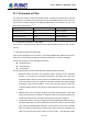
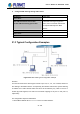
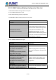
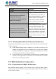
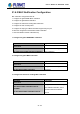
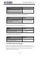
Table Of Contents
- Chapter 1 INTRODUCTION
- Chapter 2 INSTALLATION
- Chapter 3 Switch Management
- Chapter 4 Basic Switch Configuration
- Chapter 5 File System Operations
- Chapter 6 Cluster Configuration
- Chapter 7 Port Configuration
- Chapter 8 Port Isolation Function Configuration
- Chapter 9 Port Loopback Detection Function Configuration
- Chapter 10 ULDP Function Configuration
- Chapter 11 LLDP Function Operation Configuration
- Chapter 12 Port Channel Configuration
- Chapter 13 MTU Configuration
- Chapter 14 EFM OAM Configuration
- Chapter 15 PORT SECURITY
- Chapter 16 DDM Configuration
- Chapter 17 LLDP-MED
- Chapter 18 bpdu-tunnel Configuration
- Chapter 19 EEE Energy-saving Configuration
- Chapter 20 VLAN Configuration
- Chapter 21 MAC Table Configuration
- Chapter 22 MSTP Configuration
- Chapter 23 QoS Configuration
- Chapter 24 Flow-based Redirection
- Chapter 25 Flexible Q-in-Q Configuration
- Chapter 26 Layer 3 Management Configuration
- Chapter 27 ARP Scanning Prevention Function Configuration
- Chapter 28 Prevent ARP Spoofing Configuration
- Chapter 29 ARP GUARD Configuration
- Chapter 30 Gratuitous ARP Configuration
- Chapter 31 DHCP Configuration
- Chapter 32 DHCPv6 Configuration
- Chapter 33 DHCP Option 82 Configuration
- Chapter 34 DHCP Option 60 and option 43
- Chapter 35 DHCPv6 Options 37, 38
- Chapter 36 DHCP Snooping Configuration
- Chapter 37 DHCP Snooping Option 82 Configuration
- Chapter 38 IPv4 Multicast Protocol
- Chapter 39 IPv6 Multicast Protocol
- Chapter 40 Multicast VLAN
- Chapter 41 ACL Configuration
- Chapter 42 802.1x Configuration
- 42.1 Introduction to 802.1x
- 42.2 802.1x Configuration Task List
- 42.3 802.1x Application Example
- 42.4 802.1x Troubleshooting
- Chapter 43 The Number Limitation Function of MAC and IP in Port, VLAN Configuration
- Chapter 44 Operational Configuration of AM Function
- Chapter 45 Security Feature Configuration
- 45.1 Introduction to Security Feature
- 45.2 Security Feature Configuration
- 45.2.1 Prevent IP Spoofing Function Configuration Task Sequence
- 45.2.2 Prevent TCP Unauthorized Label Attack Function Configuration Task Sequence
- 45.2.3 Anti Port Cheat Function Configuration Task Sequence
- 45.2.4 Prevent TCP Fragment Attack Function Configuration Task Sequence
- 45.2.5 Prevent ICMP Fragment Attack Function Configuration Task Sequence
- 45.3 Security Feature Example
- Chapter 46 TACACS+ Configuration
- Chapter 47 RADIUS Configuration
- Chapter 48 SSL Configuration
- Chapter 49 IPv6 Security RA Configuration
- Chapter 50 MAB Configuration
- Chapter 51 PPPoE Intermediate Agent Configuration
- Chapter 52 Web Portal Configuration
- Chapter 53 VLAN-ACL Configuration
- Chapter 54 SAVI Configuration
- Chapter 55 MRPP Configuration
- Chapter 56 ULPP Configuration
- Chapter 57 ULSM Configuration
- Chapter 58 Mirror Configuration
- Chapter 59 sFlow Configuration
- Chapter 60 RSPAN Configuration
- Chapter 61 ERSPAN
- Chapter 62 SNTP Configuration
- Chapter 63 NTP Function Configuration
- Chapter 64 Summer Time Configuration
- Chapter 65 DNSv4/v6 Configuration
- Chapter 66 Monitor and Debug
- Chapter 67 Reload Switch after Specified Time
- Chapter 68 Debugging and Diagnosis for Packets Received and Sent by CPU
- Chapter 69 Dying Gasp Configuration
- Chapter 70 PoE Configuration

22-116
Chapter 22 MSTP Configuration
22.1 Introduction to MSTP
The MSTP (Multiple STP) is a new Spanning Tree Protocol which is based on the STP and the
RSTP. It runs on all the bridges of a bridged-LAN. It calculates a common and internal
spanning tree (CIST) for the bridge-LAN which consists of the bridges running the MSTP, the
RSTP and the STP. It also calculates the independent multiple spanning-tree instances (MSTI)
for each MST domain (MSTP domain). The MSTP, which adopts the RSTP for its rapid
convergence of the spanning tree, enables multiple VLANs to be mapped to the same
spanning-tree instance which is independent to other spanning-tree instances. The MSTP
provides multiple forwarding paths for data traffic and enables load balancing. Moreover,
because multiple VLANs share a same MSTI, the MSTP can reduce the number of
spanning-tree instances, which consumes less CPU resources and reduces the bandwidth
consumption.
22.2 MSTP Region
Because multiple VLANs can be mapped to a single spanning tree instance, IEEE 802.1s
committee raises the MST concept. The MST is used to make the association of a certain
VLAN to a certain spanning tree instance.
A MSTP region is composed of one or multiple bridges with the same MCID (MST
Configuration Identification) and the bridged-LAN (a certain bridge in the MSTP region is the
designated bridge of the LAN, and the bridges attaching to the LAN are not running STP). All
the bridges in the same MSTP region have the same MSID.
MSID consists of 3 attributes:
Configuration Name: Composed by digits and letters
Revision Level
Configuration Digest: VLANs mapping to spanning tree instances
The bridges with the above same 3 attributes are considered as in the same MST region.
When the MSTP calculates CIST in a bridged-LAN, an MSTP region is considered as a bridge.
See the figure below:
User’s Manual of SGS-6341 series