
SGS-6341-Series User Manual
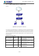
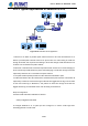
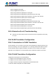
Table Of Contents
- Chapter 1 INTRODUCTION
- Chapter 2 INSTALLATION
- Chapter 3 Switch Management
- Chapter 4 Basic Switch Configuration
- Chapter 5 File System Operations
- Chapter 6 Cluster Configuration
- Chapter 7 Port Configuration
- Chapter 8 Port Isolation Function Configuration
- Chapter 9 Port Loopback Detection Function Configuration
- Chapter 10 ULDP Function Configuration
- Chapter 11 LLDP Function Operation Configuration
- Chapter 12 Port Channel Configuration
- Chapter 13 MTU Configuration
- Chapter 14 EFM OAM Configuration
- Chapter 15 PORT SECURITY
- Chapter 16 DDM Configuration
- Chapter 17 LLDP-MED
- Chapter 18 bpdu-tunnel Configuration
- Chapter 19 EEE Energy-saving Configuration
- Chapter 20 VLAN Configuration
- Chapter 21 MAC Table Configuration
- Chapter 22 MSTP Configuration
- Chapter 23 QoS Configuration
- Chapter 24 Flow-based Redirection
- Chapter 25 Flexible Q-in-Q Configuration
- Chapter 26 Layer 3 Management Configuration
- Chapter 27 ARP Scanning Prevention Function Configuration
- Chapter 28 Prevent ARP Spoofing Configuration
- Chapter 29 ARP GUARD Configuration
- Chapter 30 Gratuitous ARP Configuration
- Chapter 31 DHCP Configuration
- Chapter 32 DHCPv6 Configuration
- Chapter 33 DHCP Option 82 Configuration
- Chapter 34 DHCP Option 60 and option 43
- Chapter 35 DHCPv6 Options 37, 38
- Chapter 36 DHCP Snooping Configuration
- Chapter 37 DHCP Snooping Option 82 Configuration
- Chapter 38 IPv4 Multicast Protocol
- Chapter 39 IPv6 Multicast Protocol
- Chapter 40 Multicast VLAN
- Chapter 41 ACL Configuration
- Chapter 42 802.1x Configuration
- 42.1 Introduction to 802.1x
- 42.2 802.1x Configuration Task List
- 42.3 802.1x Application Example
- 42.4 802.1x Troubleshooting
- Chapter 43 The Number Limitation Function of MAC and IP in Port, VLAN Configuration
- Chapter 44 Operational Configuration of AM Function
- Chapter 45 Security Feature Configuration
- 45.1 Introduction to Security Feature
- 45.2 Security Feature Configuration
- 45.2.1 Prevent IP Spoofing Function Configuration Task Sequence
- 45.2.2 Prevent TCP Unauthorized Label Attack Function Configuration Task Sequence
- 45.2.3 Anti Port Cheat Function Configuration Task Sequence
- 45.2.4 Prevent TCP Fragment Attack Function Configuration Task Sequence
- 45.2.5 Prevent ICMP Fragment Attack Function Configuration Task Sequence
- 45.3 Security Feature Example
- Chapter 46 TACACS+ Configuration
- Chapter 47 RADIUS Configuration
- Chapter 48 SSL Configuration
- Chapter 49 IPv6 Security RA Configuration
- Chapter 50 MAB Configuration
- Chapter 51 PPPoE Intermediate Agent Configuration
- Chapter 52 Web Portal Configuration
- Chapter 53 VLAN-ACL Configuration
- Chapter 54 SAVI Configuration
- Chapter 55 MRPP Configuration
- Chapter 56 ULPP Configuration
- Chapter 57 ULSM Configuration
- Chapter 58 Mirror Configuration
- Chapter 59 sFlow Configuration
- Chapter 60 RSPAN Configuration
- Chapter 61 ERSPAN
- Chapter 62 SNTP Configuration
- Chapter 63 NTP Function Configuration
- Chapter 64 Summer Time Configuration
- Chapter 65 DNSv4/v6 Configuration
- Chapter 66 Monitor and Debug
- Chapter 67 Reload Switch after Specified Time
- Chapter 68 Debugging and Diagnosis for Packets Received and Sent by CPU
- Chapter 69 Dying Gasp Configuration
- Chapter 70 PoE Configuration

20-80
SP network
P
PE1
PE2
CE1
CE2
Trunk connection
Trunk connection
Unsymmetrical
connection
Unsymmetrical
connection
This port on PE1 is enabled
Q-in-Q and belong to VLAN3
On the customer port
Trunk VLAN 200-300
On the customer port
Trunk VLAN 200-300
Customer
net
work 2
Customer network 1
This port on PE1 is enabled
Q-in-Q and belong to VLAN3
Figure 20-4: Dot1q-tunnel based Intern
etworking mode
As shown in above, after being enabled on the user port, dot1q-tunnel assigns each user an
SPVLAN identification (SPVID). Here the identification of user is 3. The same SPVID should
be assigned to the same network user on different PEs. When packet reaches PE1 from CE1,
it carries the VLAN tag 200-300 of the user internal network. Since the dot1q-tunnel function is
enabled, the user port on PE1 will add on the packet another VLAN tag, of which the ID is the
SPVID assigned to the user. Afterwards, the packet will only be transmitted in VLAN3 when
traveling in the ISP internet network while carrying two VLAN tags (the inner tag is added when
entering PE1, and the outer is SPVID), whereas the VLAN information of the user network is
open to the provider network. When the packet reaches PE2 and before being forwarded to
CE2 from the client port on PE2, the outer VLAN tag is removed, then the packet CE2 received
is absolutely identical to the one sent by CE1. For the user, the role the operator network plays
between PE1 and PE2, is to provide a reliable Layer 2 link.
The technology of Dot1q-tuunel provides the ISP internet the ability of supporting many client
VLANs by only one VLAN of themselves. Both the ISP internet and the clients can configure
their own VLAN independently.
It is obvious that the dot1q-tunnel function has got the following characteristics:
Applicable through simple static configuration, no complex configuration or
maintenance is needed.
Operators will only have to assign one SPVID for each user, which increases the
number of concurrent supportable users while the users has got the ultimate
freedom in selecting and managing the VLAN IDs (select within 1~4094 at users’
will).
User’s Manual of SGS-6341 series