
SGS-6341-Series User Manual
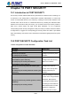
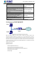

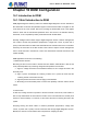

Table Of Contents
- Chapter 1 INTRODUCTION
- Chapter 2 INSTALLATION
- Chapter 3 Switch Management
- Chapter 4 Basic Switch Configuration
- Chapter 5 File System Operations
- Chapter 6 Cluster Configuration
- Chapter 7 Port Configuration
- Chapter 8 Port Isolation Function Configuration
- Chapter 9 Port Loopback Detection Function Configuration
- Chapter 10 ULDP Function Configuration
- Chapter 11 LLDP Function Operation Configuration
- Chapter 12 Port Channel Configuration
- Chapter 13 MTU Configuration
- Chapter 14 EFM OAM Configuration
- Chapter 15 PORT SECURITY
- Chapter 16 DDM Configuration
- Chapter 17 LLDP-MED
- Chapter 18 bpdu-tunnel Configuration
- Chapter 19 EEE Energy-saving Configuration
- Chapter 20 VLAN Configuration
- Chapter 21 MAC Table Configuration
- Chapter 22 MSTP Configuration
- Chapter 23 QoS Configuration
- Chapter 24 Flow-based Redirection
- Chapter 25 Flexible Q-in-Q Configuration
- Chapter 26 Layer 3 Management Configuration
- Chapter 27 ARP Scanning Prevention Function Configuration
- Chapter 28 Prevent ARP Spoofing Configuration
- Chapter 29 ARP GUARD Configuration
- Chapter 30 Gratuitous ARP Configuration
- Chapter 31 DHCP Configuration
- Chapter 32 DHCPv6 Configuration
- Chapter 33 DHCP Option 82 Configuration
- Chapter 34 DHCP Option 60 and option 43
- Chapter 35 DHCPv6 Options 37, 38
- Chapter 36 DHCP Snooping Configuration
- Chapter 37 DHCP Snooping Option 82 Configuration
- Chapter 38 IPv4 Multicast Protocol
- Chapter 39 IPv6 Multicast Protocol
- Chapter 40 Multicast VLAN
- Chapter 41 ACL Configuration
- Chapter 42 802.1x Configuration
- 42.1 Introduction to 802.1x
- 42.2 802.1x Configuration Task List
- 42.3 802.1x Application Example
- 42.4 802.1x Troubleshooting
- Chapter 43 The Number Limitation Function of MAC and IP in Port, VLAN Configuration
- Chapter 44 Operational Configuration of AM Function
- Chapter 45 Security Feature Configuration
- 45.1 Introduction to Security Feature
- 45.2 Security Feature Configuration
- 45.2.1 Prevent IP Spoofing Function Configuration Task Sequence
- 45.2.2 Prevent TCP Unauthorized Label Attack Function Configuration Task Sequence
- 45.2.3 Anti Port Cheat Function Configuration Task Sequence
- 45.2.4 Prevent TCP Fragment Attack Function Configuration Task Sequence
- 45.2.5 Prevent ICMP Fragment Attack Function Configuration Task Sequence
- 45.3 Security Feature Example
- Chapter 46 TACACS+ Configuration
- Chapter 47 RADIUS Configuration
- Chapter 48 SSL Configuration
- Chapter 49 IPv6 Security RA Configuration
- Chapter 50 MAB Configuration
- Chapter 51 PPPoE Intermediate Agent Configuration
- Chapter 52 Web Portal Configuration
- Chapter 53 VLAN-ACL Configuration
- Chapter 54 SAVI Configuration
- Chapter 55 MRPP Configuration
- Chapter 56 ULPP Configuration
- Chapter 57 ULSM Configuration
- Chapter 58 Mirror Configuration
- Chapter 59 sFlow Configuration
- Chapter 60 RSPAN Configuration
- Chapter 61 ERSPAN
- Chapter 62 SNTP Configuration
- Chapter 63 NTP Function Configuration
- Chapter 64 Summer Time Configuration
- Chapter 65 DNSv4/v6 Configuration
- Chapter 66 Monitor and Debug
- Chapter 67 Reload Switch after Specified Time
- Chapter 68 Debugging and Diagnosis for Packets Received and Sent by CPU
- Chapter 69 Dying Gasp Configuration
- Chapter 70 PoE Configuration

16-51
Chapter 16 DDM Configuration
16.1 Introduction to DDM
16.1.1 Brief Introduction to DDM
DDM (Digital Diagnostic Monitor) makes the detailed digital diagnostic function standard in
SFF-8472 MSA. It sets that the parameter signal is monitored and makes it to digitize on the
circuit board of the inner module. After that, providing the demarcated result or the digitize
measure result and the demarcated parameter which are saved in the standard memory
framework, so as to expediently read by serial interface with double cables.
Normally, intelligent fiber modules support Digital Diagnostic function. Network management
unit is able to monitor the parameters (temperature, voltage, bias current, tx power and rx
power) of the fiber module to obtain their thresholds and the real-time state of the current fiber
module by the inner MCU of the fiber module. That is able to help the network management
units to locate the fault in the fiber link, reduce the maintenance workload and enhance the
system reliability.
DDM applications are shown in the following:
1. Module lifetime forecast
Monitoring the bias current is able to forecast the laser lifetime. Administrator is able to find
some potential problems by monitoring voltage and temperature of the module.
(1)High Vcc voltage will result in the breakdown CMOS, low Vcc voltage will result in the
abnormity work.
(2)High rx power will damage the receiving module, low rx power will result that the
receiving module cannot work normally.
(3)High temperature will result in the fast aging of the hardware.
(4)Monitoring the received fiber power to monitor the capability of the link and the remote
switch.
2. Fault location
In fiber link, locating the fault is important to the fast overload of the service, fault isolation is
able to help administrator to fast locate the location of the link fault within the module (local
module or remote module) or on the link, it also reduce the time for restoring the fault of the
system.
Analyzing warning and alarm status of real-time parameters (temperature, voltage, bias
current, tx power and rx power) can fast locate the fault through Digital Diagnostic function.
Besides, the state of Tx Fault and Rx LOS is important for analyzing the fault.
User’s Manual of SGS-6341 series