
SGS-6341-Series User Manual
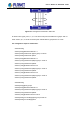
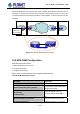
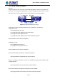
Table Of Contents
- Chapter 1 INTRODUCTION
- Chapter 2 INSTALLATION
- Chapter 3 Switch Management
- Chapter 4 Basic Switch Configuration
- Chapter 5 File System Operations
- Chapter 6 Cluster Configuration
- Chapter 7 Port Configuration
- Chapter 8 Port Isolation Function Configuration
- Chapter 9 Port Loopback Detection Function Configuration
- Chapter 10 ULDP Function Configuration
- Chapter 11 LLDP Function Operation Configuration
- Chapter 12 Port Channel Configuration
- Chapter 13 MTU Configuration
- Chapter 14 EFM OAM Configuration
- Chapter 15 PORT SECURITY
- Chapter 16 DDM Configuration
- Chapter 17 LLDP-MED
- Chapter 18 bpdu-tunnel Configuration
- Chapter 19 EEE Energy-saving Configuration
- Chapter 20 VLAN Configuration
- Chapter 21 MAC Table Configuration
- Chapter 22 MSTP Configuration
- Chapter 23 QoS Configuration
- Chapter 24 Flow-based Redirection
- Chapter 25 Flexible Q-in-Q Configuration
- Chapter 26 Layer 3 Management Configuration
- Chapter 27 ARP Scanning Prevention Function Configuration
- Chapter 28 Prevent ARP Spoofing Configuration
- Chapter 29 ARP GUARD Configuration
- Chapter 30 Gratuitous ARP Configuration
- Chapter 31 DHCP Configuration
- Chapter 32 DHCPv6 Configuration
- Chapter 33 DHCP Option 82 Configuration
- Chapter 34 DHCP Option 60 and option 43
- Chapter 35 DHCPv6 Options 37, 38
- Chapter 36 DHCP Snooping Configuration
- Chapter 37 DHCP Snooping Option 82 Configuration
- Chapter 38 IPv4 Multicast Protocol
- Chapter 39 IPv6 Multicast Protocol
- Chapter 40 Multicast VLAN
- Chapter 41 ACL Configuration
- Chapter 42 802.1x Configuration
- 42.1 Introduction to 802.1x
- 42.2 802.1x Configuration Task List
- 42.3 802.1x Application Example
- 42.4 802.1x Troubleshooting
- Chapter 43 The Number Limitation Function of MAC and IP in Port, VLAN Configuration
- Chapter 44 Operational Configuration of AM Function
- Chapter 45 Security Feature Configuration
- 45.1 Introduction to Security Feature
- 45.2 Security Feature Configuration
- 45.2.1 Prevent IP Spoofing Function Configuration Task Sequence
- 45.2.2 Prevent TCP Unauthorized Label Attack Function Configuration Task Sequence
- 45.2.3 Anti Port Cheat Function Configuration Task Sequence
- 45.2.4 Prevent TCP Fragment Attack Function Configuration Task Sequence
- 45.2.5 Prevent ICMP Fragment Attack Function Configuration Task Sequence
- 45.3 Security Feature Example
- Chapter 46 TACACS+ Configuration
- Chapter 47 RADIUS Configuration
- Chapter 48 SSL Configuration
- Chapter 49 IPv6 Security RA Configuration
- Chapter 50 MAB Configuration
- Chapter 51 PPPoE Intermediate Agent Configuration
- Chapter 52 Web Portal Configuration
- Chapter 53 VLAN-ACL Configuration
- Chapter 54 SAVI Configuration
- Chapter 55 MRPP Configuration
- Chapter 56 ULPP Configuration
- Chapter 57 ULSM Configuration
- Chapter 58 Mirror Configuration
- Chapter 59 sFlow Configuration
- Chapter 60 RSPAN Configuration
- Chapter 61 ERSPAN
- Chapter 62 SNTP Configuration
- Chapter 63 NTP Function Configuration
- Chapter 64 Summer Time Configuration
- Chapter 65 DNSv4/v6 Configuration
- Chapter 66 Monitor and Debug
- Chapter 67 Reload Switch after Specified Time
- Chapter 68 Debugging and Diagnosis for Packets Received and Sent by CPU
- Chapter 69 Dying Gasp Configuration
- Chapter 70 PoE Configuration

14-41
OAM protocol data units (OAMPDU) use destination MAC address 01-80-c2-00-00-02 of
protocol, the max. transmission rate is 10Pkt/s.
EFM OAM is established on the basis of OAM connection, it provides a link operation
management mechanism such as link monitoring, remote fault detection and remote loopback
testing, the simple introduction for EFM OAM in the following:
1. Ethernet OAM connection establishment
Ethernet OAM entity discovers remote OAM entities and establishes sessions with them by
exchanging Information OAMPDUs. EFM OAM can operate in two modes: active mode and
passive mode. One session can only be established by the OAM entity working in the active
mode and ones working in the passive mode need to wait until it receives the connection
request. After an Ethernet OAM connection is established, the Ethernet OAM entities on both
sides exchange Information OAMPDUs continuously to keep the valid Ethernet OAM
connection. If an Ethernet OAM entity receives no Information OAMPDU for five seconds, the
Ethernet OAM connection is disconnected.
2. Link Monitoring
Fault detection in an Ethernet is difficult, especially when the physical connection in the
network is not disconnected but network performance is degrading gradually. Link monitoring
is used to detect and discover link faults in various environments. EFM OAM implements link
monitoring through the exchange of Event Notification OAMPDUs. When detecting a link error
event, the local OAM entity sends an Event Notification OAMPDU to notify the remote OAM
entity. At the same time it will log information and send SNMP Trap to the network
management system. While OAM entity on the other side receives the notification, it will also
log and report it. With the log information, network administrators can keep track of network
status in time.
The link event monitored by EFM OAM means that the link happens the error event, including
Errored symbol period event, Errored frame event, Errored frame period event, Errored frame
seconds event.
Errored symbol period event: The errored symbol number can not be less than the low
threshold. (Symbol: the min data transmission unit of physical medium. It is unique for coding
system, the symbols may be different for different physical mediums, symbol rate means the
changed time of electron status per second. )
Errored frame period event: Specifying N is frame period, the errored frame number within the
period of receiving N frames can not be less than the low threshold. (Errored frame: Receiving
the errored frame detected by CRC.)
Errored frame event: The number of detected error frames over M seconds can not be less
than the low threshold.
User’s Manual of SGS-6341 series