
SGS-6341-Series User Manual
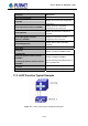
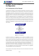
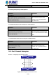
Table Of Contents
- Chapter 1 INTRODUCTION
- Chapter 2 INSTALLATION
- Chapter 3 Switch Management
- Chapter 4 Basic Switch Configuration
- Chapter 5 File System Operations
- Chapter 6 Cluster Configuration
- Chapter 7 Port Configuration
- Chapter 8 Port Isolation Function Configuration
- Chapter 9 Port Loopback Detection Function Configuration
- Chapter 10 ULDP Function Configuration
- Chapter 11 LLDP Function Operation Configuration
- Chapter 12 Port Channel Configuration
- Chapter 13 MTU Configuration
- Chapter 14 EFM OAM Configuration
- Chapter 15 PORT SECURITY
- Chapter 16 DDM Configuration
- Chapter 17 LLDP-MED
- Chapter 18 bpdu-tunnel Configuration
- Chapter 19 EEE Energy-saving Configuration
- Chapter 20 VLAN Configuration
- Chapter 21 MAC Table Configuration
- Chapter 22 MSTP Configuration
- Chapter 23 QoS Configuration
- Chapter 24 Flow-based Redirection
- Chapter 25 Flexible Q-in-Q Configuration
- Chapter 26 Layer 3 Management Configuration
- Chapter 27 ARP Scanning Prevention Function Configuration
- Chapter 28 Prevent ARP Spoofing Configuration
- Chapter 29 ARP GUARD Configuration
- Chapter 30 Gratuitous ARP Configuration
- Chapter 31 DHCP Configuration
- Chapter 32 DHCPv6 Configuration
- Chapter 33 DHCP Option 82 Configuration
- Chapter 34 DHCP Option 60 and option 43
- Chapter 35 DHCPv6 Options 37, 38
- Chapter 36 DHCP Snooping Configuration
- Chapter 37 DHCP Snooping Option 82 Configuration
- Chapter 38 IPv4 Multicast Protocol
- Chapter 39 IPv6 Multicast Protocol
- Chapter 40 Multicast VLAN
- Chapter 41 ACL Configuration
- Chapter 42 802.1x Configuration
- 42.1 Introduction to 802.1x
- 42.2 802.1x Configuration Task List
- 42.3 802.1x Application Example
- 42.4 802.1x Troubleshooting
- Chapter 43 The Number Limitation Function of MAC and IP in Port, VLAN Configuration
- Chapter 44 Operational Configuration of AM Function
- Chapter 45 Security Feature Configuration
- 45.1 Introduction to Security Feature
- 45.2 Security Feature Configuration
- 45.2.1 Prevent IP Spoofing Function Configuration Task Sequence
- 45.2.2 Prevent TCP Unauthorized Label Attack Function Configuration Task Sequence
- 45.2.3 Anti Port Cheat Function Configuration Task Sequence
- 45.2.4 Prevent TCP Fragment Attack Function Configuration Task Sequence
- 45.2.5 Prevent ICMP Fragment Attack Function Configuration Task Sequence
- 45.3 Security Feature Example
- Chapter 46 TACACS+ Configuration
- Chapter 47 RADIUS Configuration
- Chapter 48 SSL Configuration
- Chapter 49 IPv6 Security RA Configuration
- Chapter 50 MAB Configuration
- Chapter 51 PPPoE Intermediate Agent Configuration
- Chapter 52 Web Portal Configuration
- Chapter 53 VLAN-ACL Configuration
- Chapter 54 SAVI Configuration
- Chapter 55 MRPP Configuration
- Chapter 56 ULPP Configuration
- Chapter 57 ULSM Configuration
- Chapter 58 Mirror Configuration
- Chapter 59 sFlow Configuration
- Chapter 60 RSPAN Configuration
- Chapter 61 ERSPAN
- Chapter 62 SNTP Configuration
- Chapter 63 NTP Function Configuration
- Chapter 64 Summer Time Configuration
- Chapter 65 DNSv4/v6 Configuration
- Chapter 66 Monitor and Debug
- Chapter 67 Reload Switch after Specified Time
- Chapter 68 Debugging and Diagnosis for Packets Received and Sent by CPU
- Chapter 69 Dying Gasp Configuration
- Chapter 70 PoE Configuration

12-32
All ports are in full-duplex mode.
All Ports are of the same speed.
All ports are Access ports and belong to the same VLAN or are all TRUNK ports, or are
all Hybrid ports.
If the ports are all TRUNK ports or Hybrid ports, then their “Allowed VLAN” and “Native
VLAN” property should also be the same.
If Port Channel is configured manually or dynamically on switch, the system will automatically
set the port with the smallest number to be Master Port of the Port Channel. If the spanning
tree function is enabled in the switch, the spanning tree protocol will regard Port Channel as a
logical port and send BPDU frames via the master port.
Port aggregation is closely related with switch hardware. Switch allow physical port
aggregation of any two switches, maximum 14 groups and 8 ports in each port group are
supported.
Once ports are aggregated, they can be used as a normal port. Switch have a built-in
aggregation interface configuration mode, the user can perform related configuration in this
mode just like in the VLAN and physical interface configuration mode.
12.2 Brief Introduction to LACP
LACP (Link Aggregation Control Protocol) is a kind of protocol based on IEEE802.3ad
standard to implement the link dynamic aggregation. LACP protocol uses LACPDU (Link
Aggregation Control Protocol Data Unit) to exchange the information with the other end. After
LACP protocol of the port is enabled, this port will send LACPDU to the other end to notify the
system priority, the MAC address of the system, the priority of the port, the port ID and the
operation Key. After the other end receives the information, the information is compared with
the saving information of other ports to select the port which can be aggregated, accordingly,
both sides can reach an agreement about the ports join or exit the dynamic aggregation group.
The operation Key is created by LACP protocol according to the combination of
configuration (speed, duplex, basic configuration, management Key) of the ports to be
aggregated.
After the dynamic aggregation port enables LACP protocol, the management Key is 0 by
default. After the static aggregation port enables LACP, the management Key of the port is the
same with the ID of the aggregation group.
For the dynamic aggregation group, the members of the same group have the same operation
User’s Manual of SGS-6341 series