
User's Manual
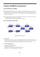
Table Of Contents
- Chapter 1 INTRODUCTION
- Chapter 2 INSTALLATION
- Chapter 3 Switch Management
- Chapter 4 Basic Switch Configuration
- Chapter 5 File System Operations
- Chapter 6 Cluster Configuration
- Chapter 7 Port Configuration
- Chapter 8 Port Isolation Function Configuration
- Chapter 9 Port Loopback Detection Function Configuration
- Chapter 10 ULDP Function Configuration
- Chapter 11 LLDP Function Operation Configuration
- Chapter 12 Port Channel Configuration
- Chapter 13 Jumbo Configuration
- Chapter 14 EFM OAM Configuration
- Chapter 15 VLAN Configuration
- Chapter 16 MAC Table Configuration
- Chapter 17 MSTP Configuration
- Chapter 18 QoS Configuration
- Chapter 19 Flow-based Redirection
- Chapter 20 Egress QoS Configuration
- Chapter 21 Flexible Q-in-Q Configuration
- Chapter 22 Layer 3 Forward Configuration
- Chapter 23 ARP Scanning Prevention Function Configuration
- Chapter 24 Prevent ARP, ND Spoofing Configuration
- Chapter 25 ARP GUARD Configuration
- Chapter 26 ARP Local Proxy Configuration
- Chapter 27 Gratuitous ARP Configuration
- Chapter 28 Keepalive Gateway Configuration
- Chapter 29 DHCP Configuration
- Chapter 30 DHCPv6 Configuration
- Chapter 31 DHCP option 82 Configuration
- Chapter 32 DHCPv6 option37, 38
- Chapter 33 DHCP Snooping Configuration
- Chapter 34 Routing Protocol Overview
- Chapter 35 Static Route
- Chapter 36 RIP
- Chapter 37 RIPng
- Chapter 38 OSPF
- Chapter 39 OSPFv3
- Chapter 40 BGP
- 40.1 Introduction to BGP
- 40.2 BGP Configuration Task List
- 40.3 Configuration Examples of BGP
- 40.3.1 Examples 1: configure BGP neighbor
- 40.3.2 Examples 2: configure BGP aggregation
- 40.3.3 Examples 3: configure BGP community attributes
- 40.3.4 Examples 4: configure BGP confederation
- 40.3.5 Examples 5: configure BGP route reflector
- 40.3.6 Examples 6: configure MED of BGP
- 40.3.7 Examples 7: example of BGP VPN
- 40.4 BGP Troubleshooting
- Chapter 41 MBGP4+
- Chapter 42 Black Hole Routing Manual
- Chapter 43 GRE Tunnel Configuration
- Chapter 44 ECMP Configuration
- Chapter 45 BFD
- Chapter 46 BGP GR
- Chapter 47 OSPF GR
- Chapter 48 IPv4 Multicast Protocol
- 48.1 IPv4 Multicast Protocol Overview
- 48.2 PIM-DM
- 48.3 PIM-SM
- 48.4 MSDP Configuration
- 48.4.1 Introduction to MSDP
- 48.4.2 Brief Introduction to MSDP Configuration Tasks
- 48.4.3 Configuration of MSDP Basic Function
- 48.4.4 Configuration of MSDP Entities
- 48.4.5 Configuration of Delivery of MSDP Packet
- 48.4.6 Configuration of Parameters of SA-cache
- 48.4.7 MSDP Configuration Examples
- 48.4.8 MSDP Troubleshooting
- 48.5 ANYCAST RP Configuration
- 48.6 PIM-SSM
- 48.7 DVMRP
- 48.8 DCSCM
- 48.9 IGMP
- 48.10 IGMP Snooping
- 48.11 IGMP Proxy Configuration
- Chapter 49 IPv6 Multicast Protocol
- Chapter 50 Multicast VLAN
- Chapter 51 ACL Configuration
- Chapter 52 802.1x Configuration
- 52.1 Introduction to 802.1x
- 52.2 802.1x Configuration Task List
- 52.3 802.1x Application Example
- 52.4 802.1x Troubleshooting
- Chapter 53 The Number Limitation Function of Port, MAC in VLAN and IP Configuration
- 53.1 Introduction to the Number Limitation Function of Port, MAC in VLAN and IP
- 53.2 The Number Limitation Function of Port, MAC in VLAN and IP Configuration Task Sequence
- 53.3 The Number Limitation Function of Port, MAC in VLAN and IP Typical Examples
- 53.4 The Number Limitation Function of Port, MAC in VLAN and IP Troubleshooting Help
- Chapter 54 Operational Configuration of AM Function
- Chapter 55 TACACS+ Configuration
- Chapter 56 RADIUS Configuration
- Chapter 57 SSL Configuration
- Chapter 58 IPv6 Security RA Configuration
- Chapter 59 VLAN-ACL Configuration
- Chapter 60 MAB Configuration
- Chapter 61 PPPoE Intermediate Agent Configuration
- Chapter 62 SAVI Configuration
- Chapter 63 Web Portal Configuration
- Chapter 64 VRRP Configuration
- Chapter 65 IPv6 VRRPv3 Configuration
- Chapter 66 MRPP Configuration
- Chapter 67 ULPP Configuration
- Chapter 68 ULSM Configuration
- Chapter 69 Mirror Configuration
- Chapter 70 RSPAN Configuration
- Chapter 71 sFlow Configuration
- Chapter 72 SNTP Configuration
- Chapter 73 NTP Function Configuration
- Chapter 74 DNSv4/v6 Configuration
- Chapter 75 Summer Time Configuration
- Chapter 76 Monitor and Debug
- Chapter 77 Reload Switch after Specified Time
- Chapter 78 Debugging and Diagnosis for Packets Received and Sent by CPU
- Chapter 79 VSF
- Chapter 80 PoE Configuration
- Chapter 81 SWITCH OPERATION
- Chapter 82 TROUBLESHOOTING
- Chapter 83 APPENDIX A
- Chapter 84 GLOSSARY

65-1
Chapter 65 IPv6 VRRPv3 Configuration
65.1 Introduction to VRRPv3
VRRPv3 is a virtual router redundancy protocol for IPv6. It is designed based on VRRP (VRRPv2) in IPv4
environment. The following is a brief introduction to it.
In a network based on TCP/IP protocol, in order to guarantee the communication between the devices which
are not physically connected, routers should be specified. At present there are two most commonly used
methods to specify routers: one is to study dynamically via routing protocols (such as internal routing
protocols RIP and OSPF); the other is to configure statically. Running dynamical routing protocol on each
terminal is unrealistic, since most operating systems for client end do not support dynamical routing protocol,
even if they do, they are limited by the overheads of management, convergence, security and many other
problems. So the common method is to adopt static routing configuration on terminal IP devices, which
usually means specify one or more default gateway for terminal devices. Static routing simplifies the
management of network and reduces the communication overheads of terminal devices, but it still has a
disadvantage: if the router acting as the default gateway breaks, the communication of all the hosts which use
this gateway as their next hop host. Even if there are more than one default gateways, before rebooting the
terminal devices, they can not switch to the new gateway. Adopting virtual router redundancy protocol (VRPR)
can effectively avoid the flaws of statically specifying gateways.
In VRRP protocol, there are two groups of import concepts: VRRP routers and virtual routers, master routers
and backup routers. VRRP routers are routers running VRRP, which are physical entities; virtual routers are
the ones created by VRRP, which are logical concepts. A group of VRRP routers cooperate to comprise a
virtual router, which acts outwardly as a logical router with a unique fixed IP address and MAC address. The
routers belonging to the same VRRP group play two mutually exclusive roles at the same time: master routers
and backup routers. One VRRP group can only have one master router other but one or more backup routers.
VRRPv3 protocol uses selection policy to select a master router from the router group to take charge of
responding ND(Neighbor Discovery) neighbor request messages(ARP in IPv4) and forwarding IP data
packets, while the other routers in the group will be in a state of waiting as backups. When the master router
has a problem for some season, the backup router will be updated to the master router after a delay of a few
seconds. Since this switch is very fast and does not need to change IP address or MAC address, it will be
transparent to terminal user systems.
In IPv6 environment, the hosts in a LAN usually learn the default gateway via neighbor discovery protocol
(NDP), which is implemented based on regularly receiving advertisement messages from routers. The NDP of
IPv6 has a mechanism called Neighbor Unreachability Detection, which checks whether a neighbor node is
failed by sending unicast neighbor request messages to it. In order to reduce the overheads of sending
neighbor request messages, these messages are only sent to those neighbor nodes which are sending flows,
and are only sent if there is no instruction of UP state of the router in a period of time. In Neighbor
Unreachability Detection, if adopting default parameters, it will take about 38 seconds to detect an
unreachable router, which is a delay not ignorable for users and might cause a time-out in some transport