
User's Manual
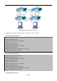
Table Of Contents
- Chapter 1 INTRODUCTION
- Chapter 2 INSTALLATION
- Chapter 3 Switch Management
- Chapter 4 Basic Switch Configuration
- Chapter 5 File System Operations
- Chapter 6 Cluster Configuration
- Chapter 7 Port Configuration
- Chapter 8 Port Isolation Function Configuration
- Chapter 9 Port Loopback Detection Function Configuration
- Chapter 10 ULDP Function Configuration
- Chapter 11 LLDP Function Operation Configuration
- Chapter 12 Port Channel Configuration
- Chapter 13 Jumbo Configuration
- Chapter 14 EFM OAM Configuration
- Chapter 15 VLAN Configuration
- Chapter 16 MAC Table Configuration
- Chapter 17 MSTP Configuration
- Chapter 18 QoS Configuration
- Chapter 19 Flow-based Redirection
- Chapter 20 Egress QoS Configuration
- Chapter 21 Flexible Q-in-Q Configuration
- Chapter 22 Layer 3 Forward Configuration
- Chapter 23 ARP Scanning Prevention Function Configuration
- Chapter 24 Prevent ARP, ND Spoofing Configuration
- Chapter 25 ARP GUARD Configuration
- Chapter 26 ARP Local Proxy Configuration
- Chapter 27 Gratuitous ARP Configuration
- Chapter 28 Keepalive Gateway Configuration
- Chapter 29 DHCP Configuration
- Chapter 30 DHCPv6 Configuration
- Chapter 31 DHCP option 82 Configuration
- Chapter 32 DHCPv6 option37, 38
- Chapter 33 DHCP Snooping Configuration
- Chapter 34 Routing Protocol Overview
- Chapter 35 Static Route
- Chapter 36 RIP
- Chapter 37 RIPng
- Chapter 38 OSPF
- Chapter 39 OSPFv3
- Chapter 40 BGP
- 40.1 Introduction to BGP
- 40.2 BGP Configuration Task List
- 40.3 Configuration Examples of BGP
- 40.3.1 Examples 1: configure BGP neighbor
- 40.3.2 Examples 2: configure BGP aggregation
- 40.3.3 Examples 3: configure BGP community attributes
- 40.3.4 Examples 4: configure BGP confederation
- 40.3.5 Examples 5: configure BGP route reflector
- 40.3.6 Examples 6: configure MED of BGP
- 40.3.7 Examples 7: example of BGP VPN
- 40.4 BGP Troubleshooting
- Chapter 41 MBGP4+
- Chapter 42 Black Hole Routing Manual
- Chapter 43 GRE Tunnel Configuration
- Chapter 44 ECMP Configuration
- Chapter 45 BFD
- Chapter 46 BGP GR
- Chapter 47 OSPF GR
- Chapter 48 IPv4 Multicast Protocol
- 48.1 IPv4 Multicast Protocol Overview
- 48.2 PIM-DM
- 48.3 PIM-SM
- 48.4 MSDP Configuration
- 48.4.1 Introduction to MSDP
- 48.4.2 Brief Introduction to MSDP Configuration Tasks
- 48.4.3 Configuration of MSDP Basic Function
- 48.4.4 Configuration of MSDP Entities
- 48.4.5 Configuration of Delivery of MSDP Packet
- 48.4.6 Configuration of Parameters of SA-cache
- 48.4.7 MSDP Configuration Examples
- 48.4.8 MSDP Troubleshooting
- 48.5 ANYCAST RP Configuration
- 48.6 PIM-SSM
- 48.7 DVMRP
- 48.8 DCSCM
- 48.9 IGMP
- 48.10 IGMP Snooping
- 48.11 IGMP Proxy Configuration
- Chapter 49 IPv6 Multicast Protocol
- Chapter 50 Multicast VLAN
- Chapter 51 ACL Configuration
- Chapter 52 802.1x Configuration
- 52.1 Introduction to 802.1x
- 52.2 802.1x Configuration Task List
- 52.3 802.1x Application Example
- 52.4 802.1x Troubleshooting
- Chapter 53 The Number Limitation Function of Port, MAC in VLAN and IP Configuration
- 53.1 Introduction to the Number Limitation Function of Port, MAC in VLAN and IP
- 53.2 The Number Limitation Function of Port, MAC in VLAN and IP Configuration Task Sequence
- 53.3 The Number Limitation Function of Port, MAC in VLAN and IP Typical Examples
- 53.4 The Number Limitation Function of Port, MAC in VLAN and IP Troubleshooting Help
- Chapter 54 Operational Configuration of AM Function
- Chapter 55 TACACS+ Configuration
- Chapter 56 RADIUS Configuration
- Chapter 57 SSL Configuration
- Chapter 58 IPv6 Security RA Configuration
- Chapter 59 VLAN-ACL Configuration
- Chapter 60 MAB Configuration
- Chapter 61 PPPoE Intermediate Agent Configuration
- Chapter 62 SAVI Configuration
- Chapter 63 Web Portal Configuration
- Chapter 64 VRRP Configuration
- Chapter 65 IPv6 VRRPv3 Configuration
- Chapter 66 MRPP Configuration
- Chapter 67 ULPP Configuration
- Chapter 68 ULSM Configuration
- Chapter 69 Mirror Configuration
- Chapter 70 RSPAN Configuration
- Chapter 71 sFlow Configuration
- Chapter 72 SNTP Configuration
- Chapter 73 NTP Function Configuration
- Chapter 74 DNSv4/v6 Configuration
- Chapter 75 Summer Time Configuration
- Chapter 76 Monitor and Debug
- Chapter 77 Reload Switch after Specified Time
- Chapter 78 Debugging and Diagnosis for Packets Received and Sent by CPU
- Chapter 79 VSF
- Chapter 80 PoE Configuration
- Chapter 81 SWITCH OPERATION
- Chapter 82 TROUBLESHOOTING
- Chapter 83 APPENDIX A
- Chapter 84 GLOSSARY

48-33
commands such debug pim event/debug pim packet please, and then copy DEBUG information in 3
minutes and send to Technology Service Center.
48.7 DVMRP
48.7.1 Introduction to DVMRP
DVMRP Protocol, namely, is “Distance Vector Multicast Routing Protocol”. It is a Multicast Routing Protocol in
dense mode, which sets up a Forward Broadcast Tree for each source in a manner similar to RIP, and sets up
a Truncation Broadcast Tree, i.e. the Shortest Path Tree to the source, for each source through dynamic
Prune/Graft.
Some of the important features of DVMRP are:
1. The routing exchange used to determine reverse path checking information is based on distance
vector (in a manner similar to RIP)
2. Routing exchange update occurs periodically (the default is 60 seconds)
3. TTL upper limit = 32 hops (and that RIP is 16)
4. Routing update includes net mask and supports CIDR
In comparison with Unicast routing, Multicast routing is a kind of reverse routing (that is, what you are
interested in is where the packets are from but not where they go), thus the information in DVMRP routing
table is used to determine if an input Multicast packet is received at the correct interface. Otherwise, the
packet will be discarded to prevent Multicast circulation.
The check which determines if the packet gets to the correct interface is called RPF check. When some
Multicast data packets get to some interface, it will determine the reverse path to the source network by
looking up DVMRP router table. If the interface data packets get to is the one which is used to send Unicast
message to the source, then the reverse path check is correct, and the data packets are forwarded out from
all downstream interfaces. If not, then probably there is failure, and the Multicast packet is discarded.
Since not all switches support Multicast, DVMRP supports tunnel multicast communication, tunnel is a
method to send multicast data report among DVMRP switches separated by switches which don’t support
multicast routing. Multicast data packets are encapsulated in unicast data packets and directly sent to the
next switch which supports multicast. DVMRP Protocol treats tunnel interface and general physical interface
equally.
If two or more switches are connected to a multi-entrance network, it is likely to transmit more than one copy
of a data packet to the sub-network. Thus a specified transmitter must be appointed. DVMRP achieves this
goal by making use of routing exchange mechanism; when two switches on the multi-entrance network
exchange routing information, they will be aware of the routing distance from each other to the source network,
thus the switch with the shortest distance to the source network will become the specified transmitter of the
sub-network. If some have the same distance, then the one with the lowest IP prevails.
After some interface of the switch is configured to Function DVMRP Protocol, the switch will multicast Probe
message to other DVMRP switches on this interface, which is used to find neighbors and detect the
capabilities of each other. If no Probe message from the neighbor is received until the neighbor is timed out,
then this neighbor is considered missing.