
User's Manual
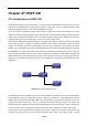

Table Of Contents
- Chapter 1 INTRODUCTION
- Chapter 2 INSTALLATION
- Chapter 3 Switch Management
- Chapter 4 Basic Switch Configuration
- Chapter 5 File System Operations
- Chapter 6 Cluster Configuration
- Chapter 7 Port Configuration
- Chapter 8 Port Isolation Function Configuration
- Chapter 9 Port Loopback Detection Function Configuration
- Chapter 10 ULDP Function Configuration
- Chapter 11 LLDP Function Operation Configuration
- Chapter 12 Port Channel Configuration
- Chapter 13 Jumbo Configuration
- Chapter 14 EFM OAM Configuration
- Chapter 15 VLAN Configuration
- Chapter 16 MAC Table Configuration
- Chapter 17 MSTP Configuration
- Chapter 18 QoS Configuration
- Chapter 19 Flow-based Redirection
- Chapter 20 Egress QoS Configuration
- Chapter 21 Flexible Q-in-Q Configuration
- Chapter 22 Layer 3 Forward Configuration
- Chapter 23 ARP Scanning Prevention Function Configuration
- Chapter 24 Prevent ARP, ND Spoofing Configuration
- Chapter 25 ARP GUARD Configuration
- Chapter 26 ARP Local Proxy Configuration
- Chapter 27 Gratuitous ARP Configuration
- Chapter 28 Keepalive Gateway Configuration
- Chapter 29 DHCP Configuration
- Chapter 30 DHCPv6 Configuration
- Chapter 31 DHCP option 82 Configuration
- Chapter 32 DHCPv6 option37, 38
- Chapter 33 DHCP Snooping Configuration
- Chapter 34 Routing Protocol Overview
- Chapter 35 Static Route
- Chapter 36 RIP
- Chapter 37 RIPng
- Chapter 38 OSPF
- Chapter 39 OSPFv3
- Chapter 40 BGP
- 40.1 Introduction to BGP
- 40.2 BGP Configuration Task List
- 40.3 Configuration Examples of BGP
- 40.3.1 Examples 1: configure BGP neighbor
- 40.3.2 Examples 2: configure BGP aggregation
- 40.3.3 Examples 3: configure BGP community attributes
- 40.3.4 Examples 4: configure BGP confederation
- 40.3.5 Examples 5: configure BGP route reflector
- 40.3.6 Examples 6: configure MED of BGP
- 40.3.7 Examples 7: example of BGP VPN
- 40.4 BGP Troubleshooting
- Chapter 41 MBGP4+
- Chapter 42 Black Hole Routing Manual
- Chapter 43 GRE Tunnel Configuration
- Chapter 44 ECMP Configuration
- Chapter 45 BFD
- Chapter 46 BGP GR
- Chapter 47 OSPF GR
- Chapter 48 IPv4 Multicast Protocol
- 48.1 IPv4 Multicast Protocol Overview
- 48.2 PIM-DM
- 48.3 PIM-SM
- 48.4 MSDP Configuration
- 48.4.1 Introduction to MSDP
- 48.4.2 Brief Introduction to MSDP Configuration Tasks
- 48.4.3 Configuration of MSDP Basic Function
- 48.4.4 Configuration of MSDP Entities
- 48.4.5 Configuration of Delivery of MSDP Packet
- 48.4.6 Configuration of Parameters of SA-cache
- 48.4.7 MSDP Configuration Examples
- 48.4.8 MSDP Troubleshooting
- 48.5 ANYCAST RP Configuration
- 48.6 PIM-SSM
- 48.7 DVMRP
- 48.8 DCSCM
- 48.9 IGMP
- 48.10 IGMP Snooping
- 48.11 IGMP Proxy Configuration
- Chapter 49 IPv6 Multicast Protocol
- Chapter 50 Multicast VLAN
- Chapter 51 ACL Configuration
- Chapter 52 802.1x Configuration
- 52.1 Introduction to 802.1x
- 52.2 802.1x Configuration Task List
- 52.3 802.1x Application Example
- 52.4 802.1x Troubleshooting
- Chapter 53 The Number Limitation Function of Port, MAC in VLAN and IP Configuration
- 53.1 Introduction to the Number Limitation Function of Port, MAC in VLAN and IP
- 53.2 The Number Limitation Function of Port, MAC in VLAN and IP Configuration Task Sequence
- 53.3 The Number Limitation Function of Port, MAC in VLAN and IP Typical Examples
- 53.4 The Number Limitation Function of Port, MAC in VLAN and IP Troubleshooting Help
- Chapter 54 Operational Configuration of AM Function
- Chapter 55 TACACS+ Configuration
- Chapter 56 RADIUS Configuration
- Chapter 57 SSL Configuration
- Chapter 58 IPv6 Security RA Configuration
- Chapter 59 VLAN-ACL Configuration
- Chapter 60 MAB Configuration
- Chapter 61 PPPoE Intermediate Agent Configuration
- Chapter 62 SAVI Configuration
- Chapter 63 Web Portal Configuration
- Chapter 64 VRRP Configuration
- Chapter 65 IPv6 VRRPv3 Configuration
- Chapter 66 MRPP Configuration
- Chapter 67 ULPP Configuration
- Chapter 68 ULSM Configuration
- Chapter 69 Mirror Configuration
- Chapter 70 RSPAN Configuration
- Chapter 71 sFlow Configuration
- Chapter 72 SNTP Configuration
- Chapter 73 NTP Function Configuration
- Chapter 74 DNSv4/v6 Configuration
- Chapter 75 Summer Time Configuration
- Chapter 76 Monitor and Debug
- Chapter 77 Reload Switch after Specified Time
- Chapter 78 Debugging and Diagnosis for Packets Received and Sent by CPU
- Chapter 79 VSF
- Chapter 80 PoE Configuration
- Chapter 81 SWITCH OPERATION
- Chapter 82 TROUBLESHOOTING
- Chapter 83 APPENDIX A
- Chapter 84 GLOSSARY

48-4
The working process of PIM-DM can be summarized as: Neighbor Discovery, Flooding & Prune, and Graft.
1. Neigh hour Discovery
After PIM-DM router is enabled, Hello message is required to discover neighbors. The network nodes which
run PIM-DM use Hello message to contact each other. PIM-DM Hello message is sent periodically.
2. Flooding & Prune of process
PIM-DM assumes all hosts on the network are ready to receive Multicast data. When some Multicast
Source begins to send data to a Multicast Group G, after receiving the Multicast packet, the router will make
RPF check first according to the Unicast table. If the check passes, the router will create a (S, G) table entry
and transmit the Multicast packet to all downstream PIM-DM nodes on the network (Flooding). If the RPF
check fails, i.e. the Multicast packet is input from the incorrect interface, and then the message is discarded.
After this procedure, in the PIM-DM Multicast domain, every node will create a (S, G) table entry. If there is
no Multicast group member in the downstream nodes, then a Prune message is sent to upstream nodes to
notify them not to transmit data of this Multicast group any more. After receiving Prune message, the
upstream nodes will delete the corresponding interface from the output interface list to which their Multicast
transmission table entry (S, G) corresponds. Thus a SPT(Shortest Path Tree, SPT) tree with source S as
root is created. The Prune process is initiated by leaf router first.
The process above is called Flooding & Prune process. Each pruned node also provides time-out
mechanics at the same time. When Prune is timed-out, the router will restart Flooding & Prune process.
The PIM-DM Flooding & Prune is periodically processed.
3. RPF Check
With RPF Check, PIM-DM makes use of existing Unicast routing table to establish a Multicast transmission
tree initiating from data source. When a Multicast packet arrives, the router will determine whether the
coming path is correct first. If the arrival interface is the interface connected to Multicast source indicated by
Unicast routing, then this Multicast packet is considered to be from the correct path. Otherwise the Multicast
packet is to be discarded as redundant message. The Unicast routing message used as path judgment can
root in any Unicast Routing Protocol, such as messages found by RIP, OSPF, etc. It doesn’t rely on any
specific Unicast Routing Protocol.
4. Assert Mechanism
If each of two Multicast routers A and B on the same LAN segment has a receiving route respectively and
both will transmit the Multicast packet to the LAN after receiving the Multicast data packet sent by the
Multicast Source S, then the downstream node Multicast router C will receive two exactly same Multicast
packets. The router needs to choose a unique transmitter through Assert mechanism after it detects this
situation. An optimal transmission path is selected through sending out Assert packet. If the priority and
cost of two or more path are same, then the node with larger IP address is taken as the upstream neighbor
of the (S, G) entry and in charge of the transmission of the (S, G) Multicast packet.
5. Graft
When the pruned downstream node needs to recover to transmission status, this node uses Graft Packet to
notify upstream nodes to restore multicast data transmission.