
User's Manual
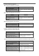
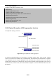
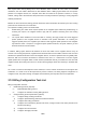
Table Of Contents
- Chapter 1 INTRODUCTION
- Chapter 2 INSTALLATION
- Chapter 3 Switch Management
- Chapter 4 Basic Switch Configuration
- Chapter 5 File System Operations
- Chapter 6 Cluster Configuration
- Chapter 7 Port Configuration
- Chapter 8 Port Isolation Function Configuration
- Chapter 9 Port Loopback Detection Function Configuration
- Chapter 10 ULDP Function Configuration
- Chapter 11 LLDP Function Operation Configuration
- Chapter 12 Port Channel Configuration
- Chapter 13 Jumbo Configuration
- Chapter 14 EFM OAM Configuration
- Chapter 15 VLAN Configuration
- Chapter 16 MAC Table Configuration
- Chapter 17 MSTP Configuration
- Chapter 18 QoS Configuration
- Chapter 19 Flow-based Redirection
- Chapter 20 Egress QoS Configuration
- Chapter 21 Flexible Q-in-Q Configuration
- Chapter 22 Layer 3 Forward Configuration
- Chapter 23 ARP Scanning Prevention Function Configuration
- Chapter 24 Prevent ARP, ND Spoofing Configuration
- Chapter 25 ARP GUARD Configuration
- Chapter 26 ARP Local Proxy Configuration
- Chapter 27 Gratuitous ARP Configuration
- Chapter 28 Keepalive Gateway Configuration
- Chapter 29 DHCP Configuration
- Chapter 30 DHCPv6 Configuration
- Chapter 31 DHCP option 82 Configuration
- Chapter 32 DHCPv6 option37, 38
- Chapter 33 DHCP Snooping Configuration
- Chapter 34 Routing Protocol Overview
- Chapter 35 Static Route
- Chapter 36 RIP
- Chapter 37 RIPng
- Chapter 38 OSPF
- Chapter 39 OSPFv3
- Chapter 40 BGP
- 40.1 Introduction to BGP
- 40.2 BGP Configuration Task List
- 40.3 Configuration Examples of BGP
- 40.3.1 Examples 1: configure BGP neighbor
- 40.3.2 Examples 2: configure BGP aggregation
- 40.3.3 Examples 3: configure BGP community attributes
- 40.3.4 Examples 4: configure BGP confederation
- 40.3.5 Examples 5: configure BGP route reflector
- 40.3.6 Examples 6: configure MED of BGP
- 40.3.7 Examples 7: example of BGP VPN
- 40.4 BGP Troubleshooting
- Chapter 41 MBGP4+
- Chapter 42 Black Hole Routing Manual
- Chapter 43 GRE Tunnel Configuration
- Chapter 44 ECMP Configuration
- Chapter 45 BFD
- Chapter 46 BGP GR
- Chapter 47 OSPF GR
- Chapter 48 IPv4 Multicast Protocol
- 48.1 IPv4 Multicast Protocol Overview
- 48.2 PIM-DM
- 48.3 PIM-SM
- 48.4 MSDP Configuration
- 48.4.1 Introduction to MSDP
- 48.4.2 Brief Introduction to MSDP Configuration Tasks
- 48.4.3 Configuration of MSDP Basic Function
- 48.4.4 Configuration of MSDP Entities
- 48.4.5 Configuration of Delivery of MSDP Packet
- 48.4.6 Configuration of Parameters of SA-cache
- 48.4.7 MSDP Configuration Examples
- 48.4.8 MSDP Troubleshooting
- 48.5 ANYCAST RP Configuration
- 48.6 PIM-SSM
- 48.7 DVMRP
- 48.8 DCSCM
- 48.9 IGMP
- 48.10 IGMP Snooping
- 48.11 IGMP Proxy Configuration
- Chapter 49 IPv6 Multicast Protocol
- Chapter 50 Multicast VLAN
- Chapter 51 ACL Configuration
- Chapter 52 802.1x Configuration
- 52.1 Introduction to 802.1x
- 52.2 802.1x Configuration Task List
- 52.3 802.1x Application Example
- 52.4 802.1x Troubleshooting
- Chapter 53 The Number Limitation Function of Port, MAC in VLAN and IP Configuration
- 53.1 Introduction to the Number Limitation Function of Port, MAC in VLAN and IP
- 53.2 The Number Limitation Function of Port, MAC in VLAN and IP Configuration Task Sequence
- 53.3 The Number Limitation Function of Port, MAC in VLAN and IP Typical Examples
- 53.4 The Number Limitation Function of Port, MAC in VLAN and IP Troubleshooting Help
- Chapter 54 Operational Configuration of AM Function
- Chapter 55 TACACS+ Configuration
- Chapter 56 RADIUS Configuration
- Chapter 57 SSL Configuration
- Chapter 58 IPv6 Security RA Configuration
- Chapter 59 VLAN-ACL Configuration
- Chapter 60 MAB Configuration
- Chapter 61 PPPoE Intermediate Agent Configuration
- Chapter 62 SAVI Configuration
- Chapter 63 Web Portal Configuration
- Chapter 64 VRRP Configuration
- Chapter 65 IPv6 VRRPv3 Configuration
- Chapter 66 MRPP Configuration
- Chapter 67 ULPP Configuration
- Chapter 68 ULSM Configuration
- Chapter 69 Mirror Configuration
- Chapter 70 RSPAN Configuration
- Chapter 71 sFlow Configuration
- Chapter 72 SNTP Configuration
- Chapter 73 NTP Function Configuration
- Chapter 74 DNSv4/v6 Configuration
- Chapter 75 Summer Time Configuration
- Chapter 76 Monitor and Debug
- Chapter 77 Reload Switch after Specified Time
- Chapter 78 Debugging and Diagnosis for Packets Received and Sent by CPU
- Chapter 79 VSF
- Chapter 80 PoE Configuration
- Chapter 81 SWITCH OPERATION
- Chapter 82 TROUBLESHOOTING
- Chapter 83 APPENDIX A
- Chapter 84 GLOSSARY

36-11
c) Layer 3 SwitchC
Configure the IP address of interface vlan 1
SwitchC#config
SwitchC(config)# interface vlan 1
Configure the IP address of interface vlan 1
SwitchC(Config-if-Vlan1)# ip address 20.1.1.2 255.255.255.0
SwitchC(Config-if-Vlan1)#exit
Initiate RIP protocol and configure the RIP segments
SwitchC(config)#router rip
SwitchC(config-router)#network vlan 1
SwitchC(config-router)#exit
36.3.2 Typical Examples of RIP aggregation function
The application topology as follows:
Figure 36-2 Typical application of RIP aggregation
As the above network topology, S2 is connected to S1 through interface vlan1, there are other 4 subnet
routers of S2, which are 192.168.21.0/24, 192.168.22.0/24, 192.168.23.0/24, 192.168.24.0/24. S2 supports
route aggregation, and to configure aggregation route 192.168.20.0/22 in interface vlan1 of S2, after that,
sending router messages to S1 through vlan1, and put the four subnet routers aggregated to one router as
192.168.20.0/22, and send to S1, and not send subnet to neighbor. It can reduce the router table of S1, save
the memory.
S1
S2
vlan1:192.168.10.1
vlan1:192.168.10.2
192.168.20.0/22
192.168.21.0/24
192.168.22.0/24
192.168.23.0/24
192.168.24.0/24