
SGS-6340 Series User Manual
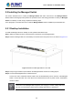
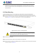
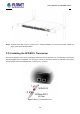
Table Of Contents
- Chapter 1 INTRODUCTION
- Chapter 2 INSTALLATION
- Chapter 3 Switch Management
- Chapter 4 Basic Switch Configuration
- Chapter 5 File System Operations
- Chapter 6 Cluster Configuration
- Chapter 7 Port Configuration
- Chapter 8 Port Isolation Function Configuration
- Chapter 9 Port Loopback Detection Function Configuration
- Chapter 10 ULDP Function Configuration
- Chapter 11 LLDP Function Operation Configuration
- Chapter 12 Port Channel Configuration
- Chapter 13 MTU Configuration
- Chapter 14 EFM OAM Configuration
- Chapter 15 PORT SECURITY
- Chapter 16 DDM Configuration
- Chapter 17 LLDP-MED
- Chapter 18 bpdu-tunnel Configuration
- Chapter 19 EEE Energy-saving Configuration
- Chapter 20 VLAN Configuration
- Chapter 21 MAC Table Configuration
- Chapter 22 MSTP Configuration
- Chapter 23 QoS Configuration
- Chapter 24 Flow-based Redirection
- Chapter 25 Flexible Q-in-Q Configuration
- Chapter 26 Layer 3 Management Configuration
- Chapter 27 ARP Scanning Prevention Function Configuration
- Chapter 28 Prevent ARP Spoofing Configuration
- Chapter 29 ARP GUARD Configuration
- Chapter 30 Gratuitous ARP Configuration
- Chapter 31 DHCP Configuration
- Chapter 32 DHCPv6 Configuration
- Chapter 33 DHCP Option 82 Configuration
- Chapter 34 DHCP Option 60 and option 43
- Chapter 35 DHCPv6 Options 37, 38
- Chapter 36 DHCP Snooping Configuration
- Chapter 37 DHCP Snooping Option 82 Configuration
- Chapter 38 IPv4 Multicast Protocol
- Chapter 39 IPv6 Multicast Protocol
- Chapter 40 Multicast VLAN
- Chapter 41 ACL Configuration
- Chapter 42 802.1x Configuration
- 42.1 Introduction to 802.1x
- 42.2 802.1x Configuration Task List
- 42.3 802.1x Application Example
- 42.4 802.1x Troubleshooting
- Chapter 43 The Number Limitation Function of MAC and IP in Port, VLAN Configuration
- Chapter 44 Operational Configuration of AM Function
- Chapter 45 Security Feature Configuration
- 45.1 Introduction to Security Feature
- 45.2 Security Feature Configuration
- 45.2.1 Prevent IP Spoofing Function Configuration Task Sequence
- 45.2.2 Prevent TCP Unauthorized Label Attack Function Configuration Task Sequence
- 45.2.3 Anti Port Cheat Function Configuration Task Sequence
- 45.2.4 Prevent TCP Fragment Attack Function Configuration Task Sequence
- 45.2.5 Prevent ICMP Fragment Attack Function Configuration Task Sequence
- 45.3 Security Feature Example
- Chapter 46 TACACS+ Configuration
- Chapter 47 RADIUS Configuration
- Chapter 48 SSL Configuration
- Chapter 49 IPv6 Security RA Configuration
- Chapter 50 MAB Configuration
- Chapter 51 PPPoE Intermediate Agent Configuration
- Chapter 52 Web Portal Configuration
- Chapter 53 VLAN-ACL Configuration
- Chapter 54 SAVI Configuration
- Chapter 55 MRPP Configuration
- Chapter 56 ULPP Configuration
- Chapter 57 ULSM Configuration
- Chapter 58 Mirror Configuration
- Chapter 59 sFlow Configuration
- Chapter 60 RSPAN Configuration
- Chapter 61 ERSPAN
- Chapter 62 SNTP Configuration
- Chapter 63 NTP Function Configuration
- Chapter 64 Summer Time Configuration
- Chapter 65 DNSv4/v6 Configuration
- Chapter 66 Monitor and Debug
- Chapter 67 Reload Switch after Specified Time
- Chapter 68 Debugging and Diagnosis for Packets Received and Sent by CPU
- Chapter 69 Dying Gasp Configuration
- Chapter 70 PoE Configuration

User’s Manual of SGS-6340 seriesT
Step 5: Supp
ly power to the Managed Switch.
Connect one end of the power cable to the Managed Switch. Connect the power plug of the power
cable into a standard wall outlet. When the Managed Switch receives power, the Power LED should
remain solid Green.
2.2.2 Rack Mounting
To install the Managed Switch in a 19-inch standard rack, please follow the instructions described below.
Step 1: Place the Managed Switch on a hard flat surface, with the front panel positioned towards the front side.
Step 2: Attach the rack-mount bracket to each side of the Managed Switch with supplied screws attached to the
package. Figure 2-14 shows how to attach brackets to one side of the Managed Switch.
Figure 2-14 Attach brackets to the Managed Switch.
You must use the screws supplied with the mounting brackets. Damage caused to the
parts by using incorrect screws would invalidate the warranty.
Step 3: Secure the brackets tightly.
Step 4: Follow the same steps to attach the second bracket to the opposite side.
Step 5: After the brackets are attached to the Managed Switch, use suitable screws to securely attach the brackets
to the rack, as shown in Figure 2-15.
27