
SGS-6340 Series User Manual
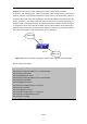
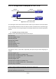


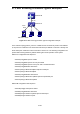
Table Of Contents
- Chapter 1 INTRODUCTION
- Chapter 2 INSTALLATION
- Chapter 3 Switch Management
- Chapter 4 Basic Switch Configuration
- Chapter 5 File System Operations
- Chapter 6 Cluster Configuration
- Chapter 7 Port Configuration
- Chapter 8 Port Isolation Function Configuration
- Chapter 9 Port Loopback Detection Function Configuration
- Chapter 10 ULDP Function Configuration
- Chapter 11 LLDP Function Operation Configuration
- Chapter 12 Port Channel Configuration
- Chapter 13 MTU Configuration
- Chapter 14 EFM OAM Configuration
- Chapter 15 PORT SECURITY
- Chapter 16 DDM Configuration
- Chapter 17 LLDP-MED
- Chapter 18 bpdu-tunnel Configuration
- Chapter 19 EEE Energy-saving Configuration
- Chapter 20 VLAN Configuration
- Chapter 21 MAC Table Configuration
- Chapter 22 MSTP Configuration
- Chapter 23 QoS Configuration
- Chapter 24 Flow-based Redirection
- Chapter 25 Flexible Q-in-Q Configuration
- Chapter 26 Layer 3 Management Configuration
- Chapter 27 ARP Scanning Prevention Function Configuration
- Chapter 28 Prevent ARP Spoofing Configuration
- Chapter 29 ARP GUARD Configuration
- Chapter 30 Gratuitous ARP Configuration
- Chapter 31 DHCP Configuration
- Chapter 32 DHCPv6 Configuration
- Chapter 33 DHCP Option 82 Configuration
- Chapter 34 DHCP Option 60 and option 43
- Chapter 35 DHCPv6 Options 37, 38
- Chapter 36 DHCP Snooping Configuration
- Chapter 37 DHCP Snooping Option 82 Configuration
- Chapter 38 IPv4 Multicast Protocol
- Chapter 39 IPv6 Multicast Protocol
- Chapter 40 Multicast VLAN
- Chapter 41 ACL Configuration
- Chapter 42 802.1x Configuration
- 42.1 Introduction to 802.1x
- 42.2 802.1x Configuration Task List
- 42.3 802.1x Application Example
- 42.4 802.1x Troubleshooting
- Chapter 43 The Number Limitation Function of MAC and IP in Port, VLAN Configuration
- Chapter 44 Operational Configuration of AM Function
- Chapter 45 Security Feature Configuration
- 45.1 Introduction to Security Feature
- 45.2 Security Feature Configuration
- 45.2.1 Prevent IP Spoofing Function Configuration Task Sequence
- 45.2.2 Prevent TCP Unauthorized Label Attack Function Configuration Task Sequence
- 45.2.3 Anti Port Cheat Function Configuration Task Sequence
- 45.2.4 Prevent TCP Fragment Attack Function Configuration Task Sequence
- 45.2.5 Prevent ICMP Fragment Attack Function Configuration Task Sequence
- 45.3 Security Feature Example
- Chapter 46 TACACS+ Configuration
- Chapter 47 RADIUS Configuration
- Chapter 48 SSL Configuration
- Chapter 49 IPv6 Security RA Configuration
- Chapter 50 MAB Configuration
- Chapter 51 PPPoE Intermediate Agent Configuration
- Chapter 52 Web Portal Configuration
- Chapter 53 VLAN-ACL Configuration
- Chapter 54 SAVI Configuration
- Chapter 55 MRPP Configuration
- Chapter 56 ULPP Configuration
- Chapter 57 ULSM Configuration
- Chapter 58 Mirror Configuration
- Chapter 59 sFlow Configuration
- Chapter 60 RSPAN Configuration
- Chapter 61 ERSPAN
- Chapter 62 SNTP Configuration
- Chapter 63 NTP Function Configuration
- Chapter 64 Summer Time Configuration
- Chapter 65 DNSv4/v6 Configuration
- Chapter 66 Monitor and Debug
- Chapter 67 Reload Switch after Specified Time
- Chapter 68 Debugging and Diagnosis for Packets Received and Sent by CPU
- Chapter 69 Dying Gasp Configuration
- Chapter 70 PoE Configuration

26.5.5 Configuration Examples of OSPF VPN
Figure 26-7 OSPF VPN Example
The above figure shows that a network consists of three Layer 3 switches in which the switchA
as PE, SwitchB and SwitchC as CE1 and CE2. The PE is connected to CE1 and CE2 through
VLAN1 and VLAN2. The routing messages are exchanged between PE and CE through OSPF
protocol.
a) SwitchA, the Layer 3 switch as PE
Configure VPN route/transmitting examples vpnb and vpnc
SwitchA#config
SwitchA(config)#ip vrf vpnb
SwitchA(config-vrf)#
SwitchA(config-vrf)#exit
SwitchA#(config)
SwitchA(config)#ip vrf vpnc
SwitchA(config-vrf)#
SwitchA(config-vrf)#exit
Associate the VLAN 1 and VLAN 2 respectively with vpnb and vpnc while configuring IP
address
SwitchA(config)#in vlan1
SwitchA(config-if-Vlan1)#ip vrf forwarding vpnb
SwitchA(config-if-Vlan1)#ip address 10.1.1.1 255.255.255.0
SwitchA(config-if-Vlan1)#exit
SwitchA(config)#in vlan2
SwitchA(config-if-Vlan2)#ip vrf forwarding vpnc
SwitchA(config-if-Vlan2)#ip address 20.1.1.1 255.255.255.0
SwitchA(config-if-Vlan2)#exit
Configure OSPF examples associated with vpnb and vpnc respectively
SwitchA(config)#
SwitchA(config)#router ospf 100 vpnb
Interface
vlan1:10.1.1.
1/24
Interface
SWITCHB
vlan1:10.1.1.
2/24
SWITCHC
SWITCHA
Interface Interface
vlan2:20.1.1.1/24 vlan1:20.1.1.2/24
26-43