
User's Manual


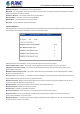

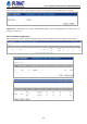


Table Of Contents
- 1. INTRODUCTION
- 2. INSTALLATION
- 3. SWITCH MANAGEMENT
- 4. WEB CONFIGURATION
- 4.1 System Information
- 4.2 Switch Management
- 4.2.1 Jumbo Frame
- 4.2.2 Interface
- 4.2.3 Statistics
- 4.2.4 VLAN
- 4.2.5 MAC Address
- 4.2.6 Port Mirror
- 4.2.7 Static Link Aggregation
- 4.2.8 LACP
- 4.2.9 Trunk Group Load Balance
- 4.2.10 Spanning Tree Protocol
- 4.2.11 IGMP Snooping
- 4.2.12 IGMP Filtering and Throttling
- 4.2.13 MLD Snooping
- 4.2.14 MVR For IPv4
- 4.2.14.1 Configure Global
- 4.2.14.2 Configure Domain
- 4.2.14.3 Show Configure Profile
- 4.2.14.4 Add Configure Profile
- 4.2.14.5 Show Associate Profile
- 4.2.14.6 Add Associate Profile
- 4.2.14.7 Configure Interface
- 4.2.14.8 Show Static Group Member
- 4.2.14.9 Add Static Group Member
- 4.2.14.10 Show Member
- 4.2.14.11 Show Query Statistics
- 4.2.14.12 Show VLAN Statistics
- 4.2.14.13 Show Port Statistics
- 4.2.14.14 Show Group Statistics
- 4.2.15 MVR For IPv6
- 4.2.15.1 Configure Global
- 4.2.15.2 Configure Domain
- 4.2.15.3 Show Configure Profile
- 4.2.15.4 Add Configure Profile
- 4.2.15.5 Show Associate Profile
- 4.2.15.6 Add Associate Profile
- 4.2.15.7 Configure Interface
- 4.2.15.8 Show Static Group Member
- 4.2.15.9 Add Static Group Member
- 4.2.15.10 Show Member
- 4.2.15.11 Show Query Statistics
- 4.2.15.12 Show VLAN Statistics
- 4.2.15.13 Show Port Statistics
- 4.2.15.14 Show Group Statistics
- 4.2.16 LLDP
- 4.2.17 ERPS
- 4.2.18 Loopback Detection
- 4.2.19 UDLD
- 4.2.20 Rate Limit
- 4.2.21 Storm Control
- 4.2.22 Stacking
- 4.2.23 Pepo
- 4.3 Route Management
- 4.4 ACL
- 4.5 CoS
- 4.6 Qu’s
- 4.7 Security
- 4.7.1 AAA
- 4.7.2 Web Authentication
- 4.7.3 802.1X
- 4.7.4 MAC Authentication
- 4.7.5 HTTPS
- 4.7.6 SSH
- 4.7.7 Port Security
- 4.7.8 DAI – Dynamic ARP Inspection
- 4.7.9 Login IP Management
- 4.7.10 DoS Protection
- 4.7.11 IPv4 DHCP Snooping
- 4.7.12 IPv6 DHCP Snooping
- 4.7.13 IPv4 Source Guard
- 4.7.14 IPv6 Source Guard
- 4.7.15 Application Filter
- 4.7.16 CPU Guard
- 4.8 Device Management
- 4.8.1 SNMP
- 4.8.2 RMON
- 4.8.3 Cluster
- 4.8.4 DNS
- 4.8.5 DHCP
- 4.8.6 OAM
- 4.8.7 CFM
- 4.8.7.1 Global Configuration
- 4.8.7.2 Interface Configuration
- 4.8.7.3 MD Management
- 4.8.7.4 MD Details
- 4.8.7.5 MA Management
- 4.8.7.6 MA Details
- 4.8.7.7 MEP Management
- 4.8.7.8 Remote MEP Management
- 4.8.7.9 Transmit Link Trace
- 4.8.7.10 Transmit Loopback
- 4.8.7.11 Transmit Delay Measure
- 4.8.7.12 Show Local MEP
- 4.8.7.13 Show Local MEP Details
- 4.8.7.14 Show Local MIP
- 4.8.7.15 Show Remote MEP
- 4.8.7.16 Show Remote MEP Details
- 4.8.7.17 Show Link Trace Cache
- 4.8.7.18 Show Fault Notification Generator
- 4.8.7.19 Show Continuity Check Error
- 4.8.8 Time Setting
- 4.8.9 Event Log
- 4.8.10 File Management
- 4.8.11 Ping
- 4.8.12 Trace Route
- 4.8.13 System Reboot
- 5. SWITCH OPERATION
- 6. TROUBLESHOOTING
- APPENDIX A: Networking Connection
- APPENDIX B : GLOSSARY

User’s Manual of SGS-5240 Series Managed Switch
167
◆Domain Name – Name of a configured ERPS ring.
◆Node State – Shows the following ERPS states:
Init – The ERPS ring has started but has not yet determined the status of the ring.
Idle – If all nodes in a ring are in this state, it means that all the links in the ring are up. This state will switch to
protection state if a link failure occurs.
Protection – If a node in this state, it means that a link failure has occurred. This state will switch to idle state if all
the failed links recover.
◆MEG Level – The maintenance entity group (MEG) level providing a communication channel for ring automatic protection
switching (R-APS) information.
◆Admin Status – Shows whether ERPS is enabled on the switch.
◆West Port – Shows the west ring port for this node.
◆East Port – Shows the east ring port for this node.
◆RPL Owner – Shows if this node is the RPL owner.
◆Control VLAN – Shows the Control VLAN ID.
◆Non ERPS Device Protection – Shows if non-standard health-check packets are sent when in protection state. Configure
Details
◆Domain Name – Name of a configured ERPS ring.
◆Admin Status – Activates the current ERPS ring.
Before enabling a ring, the global ERPS function should be enabled, the east and west ring ports configured on each node, the
RPL owner specified, and the controlVLAN configured. Once enabled, the RPL owner node and non-owner node state
machines will start, and the ring will enter idle state if no signal failures are detected.