
User's Manual


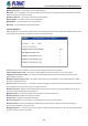

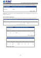


Table Of Contents
- 1. INTRODUCTION
- 2. INSTALLATION
- 3. SWITCH MANAGEMENT
- 4. WEB CONFIGURATION
- 4.1 System Information
- 4.2 Switch Management
- 4.2.1 Jumbo Frame
- 4.2.2 Interface
- 4.2.3 Statistics
- 4.2.4 VLAN
- 4.2.5 MAC Address
- 4.2.6 Port Mirror
- 4.2.7 Static Link Aggregation
- 4.2.8 LACP
- 4.2.9 Trunk Group Load Balance
- 4.2.10 Spanning Tree Protocol
- 4.2.11 IGMP Snooping
- 4.2.12 IGMP Filtering and Throttling
- 4.2.13 MLD Snooping
- 4.2.14 MVR For IPv4
- 4.2.14.1 Configure Global
- 4.2.14.2 Configure Domain
- 4.2.14.3 Show Configure Profile
- 4.2.14.4 Add Configure Profile
- 4.2.14.5 Show Associate Profile
- 4.2.14.6 Add Associate Profile
- 4.2.14.7 Configure Interface
- 4.2.14.8 Show Static Group Member
- 4.2.14.9 Add Static Group Member
- 4.2.14.10 Show Member
- 4.2.14.11 Show Query Statistics
- 4.2.14.12 Show VLAN Statistics
- 4.2.14.13 Show Port Statistics
- 4.2.14.14 Show Group Statistics
- 4.2.15 MVR For IPv6
- 4.2.15.1 Configure Global
- 4.2.15.2 Configure Domain
- 4.2.15.3 Show Configure Profile
- 4.2.15.4 Add Configure Profile
- 4.2.15.5 Show Associate Profile
- 4.2.15.6 Add Associate Profile
- 4.2.15.7 Configure Interface
- 4.2.15.8 Show Static Group Member
- 4.2.15.9 Add Static Group Member
- 4.2.15.10 Show Member
- 4.2.15.11 Show Query Statistics
- 4.2.15.12 Show VLAN Statistics
- 4.2.15.13 Show Port Statistics
- 4.2.15.14 Show Group Statistics
- 4.2.16 LLDP
- 4.2.17 ERPS
- 4.2.18 Loopback Detection
- 4.2.19 UDLD
- 4.2.20 Rate Limit
- 4.2.21 Storm Control
- 4.2.22 Stacking
- 4.2.23 Pepo
- 4.3 Route Management
- 4.4 ACL
- 4.5 CoS
- 4.6 Qu’s
- 4.7 Security
- 4.7.1 AAA
- 4.7.2 Web Authentication
- 4.7.3 802.1X
- 4.7.4 MAC Authentication
- 4.7.5 HTTPS
- 4.7.6 SSH
- 4.7.7 Port Security
- 4.7.8 DAI – Dynamic ARP Inspection
- 4.7.9 Login IP Management
- 4.7.10 DoS Protection
- 4.7.11 IPv4 DHCP Snooping
- 4.7.12 IPv6 DHCP Snooping
- 4.7.13 IPv4 Source Guard
- 4.7.14 IPv6 Source Guard
- 4.7.15 Application Filter
- 4.7.16 CPU Guard
- 4.8 Device Management
- 4.8.1 SNMP
- 4.8.2 RMON
- 4.8.3 Cluster
- 4.8.4 DNS
- 4.8.5 DHCP
- 4.8.6 OAM
- 4.8.7 CFM
- 4.8.7.1 Global Configuration
- 4.8.7.2 Interface Configuration
- 4.8.7.3 MD Management
- 4.8.7.4 MD Details
- 4.8.7.5 MA Management
- 4.8.7.6 MA Details
- 4.8.7.7 MEP Management
- 4.8.7.8 Remote MEP Management
- 4.8.7.9 Transmit Link Trace
- 4.8.7.10 Transmit Loopback
- 4.8.7.11 Transmit Delay Measure
- 4.8.7.12 Show Local MEP
- 4.8.7.13 Show Local MEP Details
- 4.8.7.14 Show Local MIP
- 4.8.7.15 Show Remote MEP
- 4.8.7.16 Show Remote MEP Details
- 4.8.7.17 Show Link Trace Cache
- 4.8.7.18 Show Fault Notification Generator
- 4.8.7.19 Show Continuity Check Error
- 4.8.8 Time Setting
- 4.8.9 Event Log
- 4.8.10 File Management
- 4.8.11 Ping
- 4.8.12 Trace Route
- 4.8.13 System Reboot
- 5. SWITCH OPERATION
- 6. TROUBLESHOOTING
- APPENDIX A: Networking Connection
- APPENDIX B : GLOSSARY

User’s Manual of SGS-5240 Series Managed Switch
162
Bit Capability
0 other or unknown
1 10BASE-T half duplex mode
2 10BASE-T full duplex mode
3 100BASE-T4
4 100BASE-TX half duplex mode
5 100BASE-TX full duplex mode
6 100BASE-T2 half duplex mode
7 100BASE-T2 full duplex mode
8 PAUSE for full-duplex links
9 Asymmetric PAUSE for full-duplex links
10 Symmetric PAUSE for full-duplex links
11 Asymmetric and Symmetric PAUSE for full-duplex links
12 1000BASE-X, -LX, -SX, -CX half duplex mode
13 1000BASE-X, -LX, -SX, -CX full duplex mode
14 1000BASE-T half duplex mode
15 1000BASE-T full duplex mode
◆Remote Port Auto-Neg Status – Shows whether port auto negotiation is enabled on a port associated with the remote
system.
◆Remote Port MAU Type – An integer value that indicates the operational MAU type of the sending device. This object
contains the integer value derived from the list position of the corresponding dot3MauType as listed in IETF RFC 3636 and is
equal to the last number in the respective dot3MauType OID. Port Details – 802.3 Extension Power Information
◆Remote Power Class – The port Class of the given port associated with the remote system (PSE – Power Sourcing
Equipment or PD – Powered Device).
◆Remote Power MDI Status – Shows whether MDI power is enabled on the given port associated with the remote system.
◆Remote Power Pairs – “Signal” means that the signal pairs only are in use, and “Spare” means that the spare pairs only are
in use.
◆Remote Power MDI Supported – Shows whether MDI power is supported on the given port associated with the remote
system.
◆Remote Power Pair Controllable – Indicates whether the pair selection can be controlled for sourcing power on the given port
associated with the remote system.
◆Remote Power Classification – This classification is used to tag different terminals on the Power over LAN network
according to their power consumption. Devices such as IP telephones, WLAN access points and others, will be classified
according to their power requirements. Port Details – 802.3 Extension Trunk Information
◆Remote Link Aggregation Capable – Shows if the remote port is not in link aggregation state and/or it does not support link
aggregation.
◆Remote Link Aggregation Status – The current aggregation status of the link.
◆Remote Link Port ID – This object contains the IEEE 802.3 aggregated port identifier, aAggPortID (IEEE 802.3-2002,
30.7.2.1.1), derived from the ifNumber of the ifIndex for the port component associated with the remote system. If the remote
port is not in link aggregation state and/or it does not support link aggregation, this value should be zero. Port Details – 802.3
Extension Frame Information
◆Remote Max Frame Size – An integer value indicating the maximum supported frame size in octets on the port component
associated with the remote system. Port Details – LLDP-MED Capability
8