
User's Manual
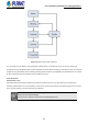
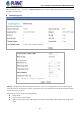
Table Of Contents
- 1. INTRODUCTION
- 2. INSTALLATION
- 3. SWITCH MANAGEMENT
- 4. WEB CONFIGURATION
- 4.1 System Information
- 4.2 Switch Management
- 4.2.1 Jumbo Frame
- 4.2.2 Interface
- 4.2.3 Statistics
- 4.2.4 VLAN
- 4.2.5 MAC Address
- 4.2.6 Port Mirror
- 4.2.7 Static Link Aggregation
- 4.2.8 LACP
- 4.2.9 Trunk Group Load Balance
- 4.2.10 Spanning Tree Protocol
- 4.2.11 IGMP Snooping
- 4.2.12 IGMP Filtering and Throttling
- 4.2.13 MLD Snooping
- 4.2.14 MVR For IPv4
- 4.2.14.1 Configure Global
- 4.2.14.2 Configure Domain
- 4.2.14.3 Show Configure Profile
- 4.2.14.4 Add Configure Profile
- 4.2.14.5 Show Associate Profile
- 4.2.14.6 Add Associate Profile
- 4.2.14.7 Configure Interface
- 4.2.14.8 Show Static Group Member
- 4.2.14.9 Add Static Group Member
- 4.2.14.10 Show Member
- 4.2.14.11 Show Query Statistics
- 4.2.14.12 Show VLAN Statistics
- 4.2.14.13 Show Port Statistics
- 4.2.14.14 Show Group Statistics
- 4.2.15 MVR For IPv6
- 4.2.15.1 Configure Global
- 4.2.15.2 Configure Domain
- 4.2.15.3 Show Configure Profile
- 4.2.15.4 Add Configure Profile
- 4.2.15.5 Show Associate Profile
- 4.2.15.6 Add Associate Profile
- 4.2.15.7 Configure Interface
- 4.2.15.8 Show Static Group Member
- 4.2.15.9 Add Static Group Member
- 4.2.15.10 Show Member
- 4.2.15.11 Show Query Statistics
- 4.2.15.12 Show VLAN Statistics
- 4.2.15.13 Show Port Statistics
- 4.2.15.14 Show Group Statistics
- 4.2.16 LLDP
- 4.2.17 ERPS
- 4.2.18 Loopback Detection
- 4.2.19 UDLD
- 4.2.20 Rate Limit
- 4.2.21 Storm Control
- 4.2.22 Stacking
- 4.2.23 Pepo
- 4.3 Route Management
- 4.4 ACL
- 4.5 CoS
- 4.6 Qu’s
- 4.7 Security
- 4.7.1 AAA
- 4.7.2 Web Authentication
- 4.7.3 802.1X
- 4.7.4 MAC Authentication
- 4.7.5 HTTPS
- 4.7.6 SSH
- 4.7.7 Port Security
- 4.7.8 DAI – Dynamic ARP Inspection
- 4.7.9 Login IP Management
- 4.7.10 DoS Protection
- 4.7.11 IPv4 DHCP Snooping
- 4.7.12 IPv6 DHCP Snooping
- 4.7.13 IPv4 Source Guard
- 4.7.14 IPv6 Source Guard
- 4.7.15 Application Filter
- 4.7.16 CPU Guard
- 4.8 Device Management
- 4.8.1 SNMP
- 4.8.2 RMON
- 4.8.3 Cluster
- 4.8.4 DNS
- 4.8.5 DHCP
- 4.8.6 OAM
- 4.8.7 CFM
- 4.8.7.1 Global Configuration
- 4.8.7.2 Interface Configuration
- 4.8.7.3 MD Management
- 4.8.7.4 MD Details
- 4.8.7.5 MA Management
- 4.8.7.6 MA Details
- 4.8.7.7 MEP Management
- 4.8.7.8 Remote MEP Management
- 4.8.7.9 Transmit Link Trace
- 4.8.7.10 Transmit Loopback
- 4.8.7.11 Transmit Delay Measure
- 4.8.7.12 Show Local MEP
- 4.8.7.13 Show Local MEP Details
- 4.8.7.14 Show Local MIP
- 4.8.7.15 Show Remote MEP
- 4.8.7.16 Show Remote MEP Details
- 4.8.7.17 Show Link Trace Cache
- 4.8.7.18 Show Fault Notification Generator
- 4.8.7.19 Show Continuity Check Error
- 4.8.8 Time Setting
- 4.8.9 Event Log
- 4.8.10 File Management
- 4.8.11 Ping
- 4.8.12 Trace Route
- 4.8.13 System Reboot
- 5. SWITCH OPERATION
- 6. TROUBLESHOOTING
- APPENDIX A: Networking Connection
- APPENDIX B : GLOSSARY

User’s Manual of SGS-5240 Series Managed Switch
90
◆BPDU Flooding – Configures the system to flood BPDUs to all other ports on the switch or just to all other ports in the
same VLAN when spanning tree is disabled globally on the switch or disabled on a specific port.
To VLAN: Floods BPDUs to all other ports within the receiving port’s native VLAN (i.e., as determined by port’s
PVID). This is the default.
To All: Floods BPDUs to all other ports on the switch.
The setting has no effect if BPDU flooding is disabled on a port.
The following attributes are based on RSTP, but also apply to STP since the switch uses a backwards-compatible subset of
RSTP to implement STP, and also apply to MSTP which is based on RSTP according to the standard:
◆Path Cost Method – The path cost is used to determine the best path between devices. The path cost method is used to
determine the range of values that can be assigned to each interface.
Long: Specifies 32-bit based values that range from 1-200,000,000.
(This is the default.)
Short: Specifies 16-bit based values that range from 1-65535.
◆Transmission Limit – The maximum transmission rate for BPDUs is specified by setting the minimum interval between the
transmission of consecutive protocol messages. (Range: 1-10; Default: 3)
When the Switch Becomes Root
◆Hello Time – Interval (in seconds) at which the root device transmits a configuration message.
Default: 2
Minimum: 1
Maximum: The lower of 10 or [(Max. Message Age / 2) -1]
◆Maximum Age – The maximum time (in seconds) a device can wait without receiving a configuration message before
attempting to reconverge. All device ports (except for designated ports) should receive configuration messages at regular
intervals. Any port that ages out STA information (provided in the last configuration message) becomes the designated port for
the attached LAN. If it is a root port, a new root port is selected from among the device ports attached to the network.
(References to “ports” in this section mean “interfaces,” which includes both ports and groups.)
Default: 20
Minimum: The higher of 6 or [2 x (Hello Time + 1)]
Maximum: The lower of 40 or [2 x (Forward Delay - 1)]
◆Forward Delay – The maximum time (in seconds) this device will wait before changing states (i.e., discarding to learning to
forwarding). This delay is required because every device must receive information about topology changes before it starts to
forward frames. In addition, each port needs time to listen for conflicting information that would make it return to a discarding
state; otherwise, temporary data loops might result.
Default: 15
Minimum: The higher of 4 or [(Max. Message Age / 2) + 1]
Maximum: 30
RSTP does not depend on the forward delay timer in most cases. It is able to confirm that a port can transition to the forwarding
state without having to rely on any timer configuration. To achieve fast convergence, RSTP relies on the use of edge ports, and
automatic detection of point-to-point link types, both of which allow a port to directly transition to the forwarding state.