
User's Manual
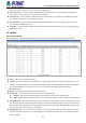
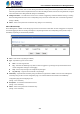
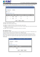
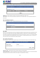
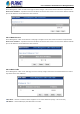
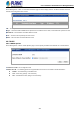
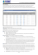
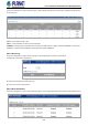
Table Of Contents
- 1. INTRODUCTION
- 2. INSTALLATION
- 3. SWITCH MANAGEMENT
- 4. WEB CONFIGURATION
- 4.1 System Information
- 4.2 Switch Management
- 4.2.1 Jumbo Frame
- 4.2.2 Interface
- 4.2.3 Statistics
- 4.2.4 VLAN
- 4.2.5 MAC Address
- 4.2.6 Port Mirror
- 4.2.7 Static Link Aggregation
- 4.2.8 LACP
- 4.2.9 Trunk Group Load Balance
- 4.2.10 Spanning Tree Protocol
- 4.2.11 IGMP Snooping
- 4.2.12 IGMP Filtering and Throttling
- 4.2.13 MLD Snooping
- 4.2.14 MVR For IPv4
- 4.2.14.1 Configure Global
- 4.2.14.2 Configure Domain
- 4.2.14.3 Show Configure Profile
- 4.2.14.4 Add Configure Profile
- 4.2.14.5 Show Associate Profile
- 4.2.14.6 Add Associate Profile
- 4.2.14.7 Configure Interface
- 4.2.14.8 Show Static Group Member
- 4.2.14.9 Add Static Group Member
- 4.2.14.10 Show Member
- 4.2.14.11 Show Query Statistics
- 4.2.14.12 Show VLAN Statistics
- 4.2.14.13 Show Port Statistics
- 4.2.14.14 Show Group Statistics
- 4.2.15 MVR For IPv6
- 4.2.15.1 Configure Global
- 4.2.15.2 Configure Domain
- 4.2.15.3 Show Configure Profile
- 4.2.15.4 Add Configure Profile
- 4.2.15.5 Show Associate Profile
- 4.2.15.6 Add Associate Profile
- 4.2.15.7 Configure Interface
- 4.2.15.8 Show Static Group Member
- 4.2.15.9 Add Static Group Member
- 4.2.15.10 Show Member
- 4.2.15.11 Show Query Statistics
- 4.2.15.12 Show VLAN Statistics
- 4.2.15.13 Show Port Statistics
- 4.2.15.14 Show Group Statistics
- 4.2.16 LLDP
- 4.2.17 ERPS
- 4.2.18 Loopback Detection
- 4.2.19 UDLD
- 4.2.20 Rate Limit
- 4.2.21 Storm Control
- 4.2.22 Stacking
- 4.2.23 Pepo
- 4.3 Route Management
- 4.4 ACL
- 4.5 CoS
- 4.6 Qu’s
- 4.7 Security
- 4.7.1 AAA
- 4.7.2 Web Authentication
- 4.7.3 802.1X
- 4.7.4 MAC Authentication
- 4.7.5 HTTPS
- 4.7.6 SSH
- 4.7.7 Port Security
- 4.7.8 DAI – Dynamic ARP Inspection
- 4.7.9 Login IP Management
- 4.7.10 DoS Protection
- 4.7.11 IPv4 DHCP Snooping
- 4.7.12 IPv6 DHCP Snooping
- 4.7.13 IPv4 Source Guard
- 4.7.14 IPv6 Source Guard
- 4.7.15 Application Filter
- 4.7.16 CPU Guard
- 4.8 Device Management
- 4.8.1 SNMP
- 4.8.2 RMON
- 4.8.3 Cluster
- 4.8.4 DNS
- 4.8.5 DHCP
- 4.8.6 OAM
- 4.8.7 CFM
- 4.8.7.1 Global Configuration
- 4.8.7.2 Interface Configuration
- 4.8.7.3 MD Management
- 4.8.7.4 MD Details
- 4.8.7.5 MA Management
- 4.8.7.6 MA Details
- 4.8.7.7 MEP Management
- 4.8.7.8 Remote MEP Management
- 4.8.7.9 Transmit Link Trace
- 4.8.7.10 Transmit Loopback
- 4.8.7.11 Transmit Delay Measure
- 4.8.7.12 Show Local MEP
- 4.8.7.13 Show Local MEP Details
- 4.8.7.14 Show Local MIP
- 4.8.7.15 Show Remote MEP
- 4.8.7.16 Show Remote MEP Details
- 4.8.7.17 Show Link Trace Cache
- 4.8.7.18 Show Fault Notification Generator
- 4.8.7.19 Show Continuity Check Error
- 4.8.8 Time Setting
- 4.8.9 Event Log
- 4.8.10 File Management
- 4.8.11 Ping
- 4.8.12 Trace Route
- 4.8.13 System Reboot
- 5. SWITCH OPERATION
- 6. TROUBLESHOOTING
- APPENDIX A: Networking Connection
- APPENDIX B : GLOSSARY

User’s Manual of SGS-5240 Series Managed Switch
259
4.8.6 OAM
4.8.6.1 Interface
The Device Management > OAM > Interface page is used to enable OAM functionality on the selected port. Not all CPEs
support operation and maintenance functions, so OAM is therefore disabled by default. If a CPE supports OAM, this
functionality must first be enabled on the connected port to gain access to the configuration functions provided under the OAM
menu.
◆Port – Port identifier. (Range: 1-28)
◆Admin Status – Enables or disables OAM functions. (Default: Disabled)
◆Operation State – Shows the operational state between the local and remote OAM devices. This value is always “disabled” if
OAM is disabled on the local interface. OAM Operation State
◆Mode – Sets the OAM operation mode. (Default: Active)
Active – All OAM functions are enabled.
Passive – All OAM functions are enabled, except for OAM discovery, sending variable request OAMPDUs, and
sending loopback control OAMPDUs.
◆Critical Link Event – Controls reporting of critical link events to its OAM peer.
Dying Gasp – If an unrecoverable condition occurs, the local OAM entity (i.e., this switch) indicates this by
immediately sending a trap message. (Default: Enabled) Dying gasp events are caused by an unrecoverable failure,
such as a power failure or device reset.
Critical Event – If a critical event occurs, the local OAM entity indicates this to its peer by setting the appropriate
flag in the next OAMPDU to be sent and stores this information in its OAM event log. (Default: Enabled) Critical
events include various failures, such as abnormal voltage fluctuations, out-of-range temperature detected, fan
failure, CRC error in flash memory, insufficient memory, or other hardware faults.
◆Errored Frame – Controls reporting of errored frame link events. An errored frame is a frame in which one or more bits are
errored. An errored frame link event occurs if the threshold is reached or exceeded within the specified period. If reporting is
enabled and an errored frame link event occurs, the local OAM entity (this switch) sends an Event Notification OAMPDU to the
remote OAM entity. The Errored Frame Event TLV includes the number of errored frames detected during the specified period.
Status – Enables reporting of errored frame link events. (Default: Enabled)
Window Size – The period of time in which to check the reporting threshold for errored frame link events. (Range:
10-65535 in units of 10 milliseconds; Default: 10 units of 10 milliseconds, or the equivalent of 1 second)
Threshold Count – The threshold for errored frame link events. (Range: 1-65535; Default: 1)