
User's Manual
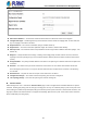
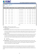
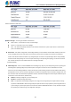
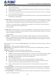
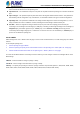
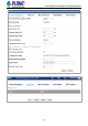
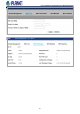
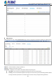
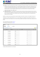
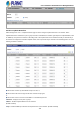
Table Of Contents
- 1. INTRODUCTION
- 2. INSTALLATION
- 3. SWITCH MANAGEMENT
- 4. WEB CONFIGURATION
- 4.1 System Information
- 4.2 Switch Management
- 4.2.1 Jumbo Frame
- 4.2.2 Interface
- 4.2.3 Statistics
- 4.2.4 VLAN
- 4.2.5 MAC Address
- 4.2.6 Port Mirror
- 4.2.7 Static Link Aggregation
- 4.2.8 LACP
- 4.2.9 Trunk Group Load Balance
- 4.2.10 Spanning Tree Protocol
- 4.2.11 IGMP Snooping
- 4.2.12 IGMP Filtering and Throttling
- 4.2.13 MLD Snooping
- 4.2.14 MVR For IPv4
- 4.2.14.1 Configure Global
- 4.2.14.2 Configure Domain
- 4.2.14.3 Show Configure Profile
- 4.2.14.4 Add Configure Profile
- 4.2.14.5 Show Associate Profile
- 4.2.14.6 Add Associate Profile
- 4.2.14.7 Configure Interface
- 4.2.14.8 Show Static Group Member
- 4.2.14.9 Add Static Group Member
- 4.2.14.10 Show Member
- 4.2.14.11 Show Query Statistics
- 4.2.14.12 Show VLAN Statistics
- 4.2.14.13 Show Port Statistics
- 4.2.14.14 Show Group Statistics
- 4.2.15 MVR For IPv6
- 4.2.15.1 Configure Global
- 4.2.15.2 Configure Domain
- 4.2.15.3 Show Configure Profile
- 4.2.15.4 Add Configure Profile
- 4.2.15.5 Show Associate Profile
- 4.2.15.6 Add Associate Profile
- 4.2.15.7 Configure Interface
- 4.2.15.8 Show Static Group Member
- 4.2.15.9 Add Static Group Member
- 4.2.15.10 Show Member
- 4.2.15.11 Show Query Statistics
- 4.2.15.12 Show VLAN Statistics
- 4.2.15.13 Show Port Statistics
- 4.2.15.14 Show Group Statistics
- 4.2.16 LLDP
- 4.2.17 ERPS
- 4.2.18 Loopback Detection
- 4.2.19 UDLD
- 4.2.20 Rate Limit
- 4.2.21 Storm Control
- 4.2.22 Stacking
- 4.2.23 Pepo
- 4.3 Route Management
- 4.4 ACL
- 4.5 CoS
- 4.6 Qu’s
- 4.7 Security
- 4.7.1 AAA
- 4.7.2 Web Authentication
- 4.7.3 802.1X
- 4.7.4 MAC Authentication
- 4.7.5 HTTPS
- 4.7.6 SSH
- 4.7.7 Port Security
- 4.7.8 DAI – Dynamic ARP Inspection
- 4.7.9 Login IP Management
- 4.7.10 DoS Protection
- 4.7.11 IPv4 DHCP Snooping
- 4.7.12 IPv6 DHCP Snooping
- 4.7.13 IPv4 Source Guard
- 4.7.14 IPv6 Source Guard
- 4.7.15 Application Filter
- 4.7.16 CPU Guard
- 4.8 Device Management
- 4.8.1 SNMP
- 4.8.2 RMON
- 4.8.3 Cluster
- 4.8.4 DNS
- 4.8.5 DHCP
- 4.8.6 OAM
- 4.8.7 CFM
- 4.8.7.1 Global Configuration
- 4.8.7.2 Interface Configuration
- 4.8.7.3 MD Management
- 4.8.7.4 MD Details
- 4.8.7.5 MA Management
- 4.8.7.6 MA Details
- 4.8.7.7 MEP Management
- 4.8.7.8 Remote MEP Management
- 4.8.7.9 Transmit Link Trace
- 4.8.7.10 Transmit Loopback
- 4.8.7.11 Transmit Delay Measure
- 4.8.7.12 Show Local MEP
- 4.8.7.13 Show Local MEP Details
- 4.8.7.14 Show Local MIP
- 4.8.7.15 Show Remote MEP
- 4.8.7.16 Show Remote MEP Details
- 4.8.7.17 Show Link Trace Cache
- 4.8.7.18 Show Fault Notification Generator
- 4.8.7.19 Show Continuity Check Error
- 4.8.8 Time Setting
- 4.8.9 Event Log
- 4.8.10 File Management
- 4.8.11 Ping
- 4.8.12 Trace Route
- 4.8.13 System Reboot
- 5. SWITCH OPERATION
- 6. TROUBLESHOOTING
- APPENDIX A: Networking Connection
- APPENDIX B : GLOSSARY

User’s Manual of SGS-5240 Series Managed Switch
91
Configuration Settings for MSTP
Max Instance Numbers – The maximum number of MSTP instances to which this switch can be assigned.
Configuration Digest – An MD5 signature key that contains the VLAN ID to MST ID mapping table. In other words, this
key is a mapping of all VLANs to the CIST.
Region Revision
4 – The revision for this MSTI. (Range: 0-65535; Default: 0)
Region Name
4 – The name for this MSTI. (Maximum length: 32 characters; switch’s MAC address)
Max Hop Count – The maximum number of hops allowed in the MST region before a BPDU is discarded. (Range: 1-40;
Default: 20)
Bridge ID – A unique identifier for this bridge, consisting of the bridge priority, the MST Instance ID 0 for the Common
Spanning Tree when spanning tree type is set to MSTP, and MAC address (where the address is taken from the switch
system).
Designated Root – The priority and MAC address of the device in the Spanning Tree that this switch has accepted as the
root device.
Root Port – The number of the port on this switch that is closest to the root. This switch communicates with the root
device through this port. If there is no root port, then this switch has been accepted as the root device of the Spanning
Tree network.
Root Path Cost – The path cost from the root port on this switch to the root device.
Configuration Changes – The number of times the Spanning Tree has been reconfigured.
Last Topology Change – Time since the Spanning Tree was last reconfigured.
Interface Status
Switch Management > STP > STP-RSTP> Interface Status page is used to configure RSTP and MSTP attributes for specific
interfaces, including port priority, path cost, link type, and edge port. You may use a different priority or path cost for ports of the
same media type to indicate the preferred path, link type to indicate a point-to-point connection or shared media connection, and
edge port to indicate if the attached device can support fast forwarding. (References to “ports” in this section means “interfaces,”
which includes both ports and groups.)