
User's Manual
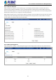
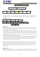
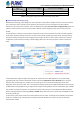
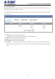
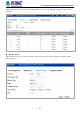
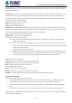
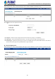
Table Of Contents
- 1. INTRODUCTION
- 2. INSTALLATION
- 3. SWITCH MANAGEMENT
- 4. WEB CONFIGURATION
- 4.1 System Information
- 4.2 Switch Management
- 4.2.1 Jumbo Frame
- 4.2.2 Interface
- 4.2.3 Statistics
- 4.2.4 VLAN
- 4.2.5 MAC Address
- 4.2.6 Port Mirror
- 4.2.7 Static Link Aggregation
- 4.2.8 LACP
- 4.2.9 Trunk Group Load Balance
- 4.2.10 Spanning Tree Protocol
- 4.2.11 IGMP Snooping
- 4.2.12 IGMP Filtering and Throttling
- 4.2.13 MLD Snooping
- 4.2.14 MVR For IPv4
- 4.2.14.1 Configure Global
- 4.2.14.2 Configure Domain
- 4.2.14.3 Show Configure Profile
- 4.2.14.4 Add Configure Profile
- 4.2.14.5 Show Associate Profile
- 4.2.14.6 Add Associate Profile
- 4.2.14.7 Configure Interface
- 4.2.14.8 Show Static Group Member
- 4.2.14.9 Add Static Group Member
- 4.2.14.10 Show Member
- 4.2.14.11 Show Query Statistics
- 4.2.14.12 Show VLAN Statistics
- 4.2.14.13 Show Port Statistics
- 4.2.14.14 Show Group Statistics
- 4.2.15 MVR For IPv6
- 4.2.15.1 Configure Global
- 4.2.15.2 Configure Domain
- 4.2.15.3 Show Configure Profile
- 4.2.15.4 Add Configure Profile
- 4.2.15.5 Show Associate Profile
- 4.2.15.6 Add Associate Profile
- 4.2.15.7 Configure Interface
- 4.2.15.8 Show Static Group Member
- 4.2.15.9 Add Static Group Member
- 4.2.15.10 Show Member
- 4.2.15.11 Show Query Statistics
- 4.2.15.12 Show VLAN Statistics
- 4.2.15.13 Show Port Statistics
- 4.2.15.14 Show Group Statistics
- 4.2.16 LLDP
- 4.2.17 ERPS
- 4.2.18 Loopback Detection
- 4.2.19 UDLD
- 4.2.20 Rate Limit
- 4.2.21 Storm Control
- 4.2.22 Stacking
- 4.2.23 Pepo
- 4.3 Route Management
- 4.4 ACL
- 4.5 CoS
- 4.6 Qu’s
- 4.7 Security
- 4.7.1 AAA
- 4.7.2 Web Authentication
- 4.7.3 802.1X
- 4.7.4 MAC Authentication
- 4.7.5 HTTPS
- 4.7.6 SSH
- 4.7.7 Port Security
- 4.7.8 DAI – Dynamic ARP Inspection
- 4.7.9 Login IP Management
- 4.7.10 DoS Protection
- 4.7.11 IPv4 DHCP Snooping
- 4.7.12 IPv6 DHCP Snooping
- 4.7.13 IPv4 Source Guard
- 4.7.14 IPv6 Source Guard
- 4.7.15 Application Filter
- 4.7.16 CPU Guard
- 4.8 Device Management
- 4.8.1 SNMP
- 4.8.2 RMON
- 4.8.3 Cluster
- 4.8.4 DNS
- 4.8.5 DHCP
- 4.8.6 OAM
- 4.8.7 CFM
- 4.8.7.1 Global Configuration
- 4.8.7.2 Interface Configuration
- 4.8.7.3 MD Management
- 4.8.7.4 MD Details
- 4.8.7.5 MA Management
- 4.8.7.6 MA Details
- 4.8.7.7 MEP Management
- 4.8.7.8 Remote MEP Management
- 4.8.7.9 Transmit Link Trace
- 4.8.7.10 Transmit Loopback
- 4.8.7.11 Transmit Delay Measure
- 4.8.7.12 Show Local MEP
- 4.8.7.13 Show Local MEP Details
- 4.8.7.14 Show Local MIP
- 4.8.7.15 Show Remote MEP
- 4.8.7.16 Show Remote MEP Details
- 4.8.7.17 Show Link Trace Cache
- 4.8.7.18 Show Fault Notification Generator
- 4.8.7.19 Show Continuity Check Error
- 4.8.8 Time Setting
- 4.8.9 Event Log
- 4.8.10 File Management
- 4.8.11 Ping
- 4.8.12 Trace Route
- 4.8.13 System Reboot
- 5. SWITCH OPERATION
- 6. TROUBLESHOOTING
- APPENDIX A: Networking Connection
- APPENDIX B : GLOSSARY

User’s Manual of SGS-5240 Series Managed Switch
59
4.2.4.3 GVRP
Switch Management > VLAN > GVRP page is used to enable GVRP globally on the switch, or to enable GVRP and adjust the
protocol timers per interface.
◆GVRP Status – GVRP defines a way for switches to exchange VLAN information in order to register VLAN members on ports
across the network. VLANs are dynamically configured based on join messages issued by host devices and propagated
throughout the network. GVRP must be enabled to permit automatic VLAN registration, and to support VLANs which extend
beyond the local switch. (Default: Disabled)
◆Interface – Displays a list of ports or group.
◆Port – Port Identifier. (Range: 1-28)
◆Group – Group Identifier. (Range: 1-12)
◆GVRP Status – Enables/disables GVRP for the interface. GVRP must be globally enabled for the switch before this setting
can take effect (using the Configure General page). When disabled, any GVRP packets received on this port will be discarded
and no GVRP registrations will be propagated from other ports. (Default: Disabled)
GVRP cannot be enabled for ports set to Access mode
◆GVRP Timers – Timer settings must follow this rule:
2 x (join timer) < leave timer < leaveAll timer
Join – The interval between transmitting requests/queries to participate in a VLAN group. (Range: 20-1000
centiseconds; Default: 20)
Leave – The interval a port waits before leaving a VLAN group. This time should be set to more than twice the
join time. This ensures that after a Leave or LeaveAll message has been issued, the applicants can rejoin before
the port actually leaves the group.
(Range: 60-3000 centiseconds; Default: 60)
LeaveAll – The interval between sending out a LeaveAll query message for VLAN group participants and the
port leaving the group. This interval should be considerably larger than the Leave Time to minimize the amount
of traffic generated by nodes rejoining the group. (Range: 500-18000 centiseconds; Default: 1000)
Show Dynamic VLAN – Show VLAN
VLAN ID – Identifier of a VLAN this switch has joined through GVRP.
VLAN Name – Name of a VLAN this switch has joined through GVRP.
Status – Indicates if this VLAN is currently operational.
(Display Values: Enabled, Disabled)
Show Dynamic VLAN – Show VLAN Member
◆VLAN – Identifier of a VLAN this switch has joined through GVRP.
◆Interface – Displays a list of ports or groups which have joined the selected VLAN through GVRP.
4.2.4.4 Protocol VLAN
To configure protocol-based VLANs, follow these steps:
1. First configure VLAN groups for the protocols you want to use. Although not mandatory, we suggest configuring a
separate VLAN for each major protocol running on your network. Do not add port members at this time.
2. Create a protocol group for each of the protocols you want to assign to a VLAN using the Configure Protocol (Add)
page.
3. Then map the protocol for each interface to the appropriate VLAN using the Configure Interface (Add) page.
When MAC-based, IP subnet-based, and protocol-based VLANs are supported concurrently, priority is applied in this sequence,
and then port-based VLANs last.