
User's Manual
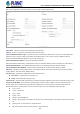
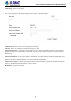
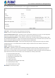
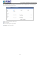
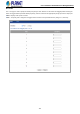
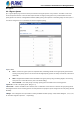
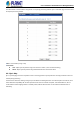
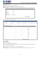
Table Of Contents
- 1. INTRODUCTION
- 2. INSTALLATION
- 3. SWITCH MANAGEMENT
- 4. WEB CONFIGURATION
- 4.1 System Information
- 4.2 Switch Management
- 4.2.1 Jumbo Frame
- 4.2.2 Interface
- 4.2.3 Statistics
- 4.2.4 VLAN
- 4.2.5 MAC Address
- 4.2.6 Port Mirror
- 4.2.7 Static Link Aggregation
- 4.2.8 LACP
- 4.2.9 Trunk Group Load Balance
- 4.2.10 Spanning Tree Protocol
- 4.2.11 IGMP Snooping
- 4.2.12 IGMP Filtering and Throttling
- 4.2.13 MLD Snooping
- 4.2.14 MVR For IPv4
- 4.2.14.1 Configure Global
- 4.2.14.2 Configure Domain
- 4.2.14.3 Show Configure Profile
- 4.2.14.4 Add Configure Profile
- 4.2.14.5 Show Associate Profile
- 4.2.14.6 Add Associate Profile
- 4.2.14.7 Configure Interface
- 4.2.14.8 Show Static Group Member
- 4.2.14.9 Add Static Group Member
- 4.2.14.10 Show Member
- 4.2.14.11 Show Query Statistics
- 4.2.14.12 Show VLAN Statistics
- 4.2.14.13 Show Port Statistics
- 4.2.14.14 Show Group Statistics
- 4.2.15 MVR For IPv6
- 4.2.15.1 Configure Global
- 4.2.15.2 Configure Domain
- 4.2.15.3 Show Configure Profile
- 4.2.15.4 Add Configure Profile
- 4.2.15.5 Show Associate Profile
- 4.2.15.6 Add Associate Profile
- 4.2.15.7 Configure Interface
- 4.2.15.8 Show Static Group Member
- 4.2.15.9 Add Static Group Member
- 4.2.15.10 Show Member
- 4.2.15.11 Show Query Statistics
- 4.2.15.12 Show VLAN Statistics
- 4.2.15.13 Show Port Statistics
- 4.2.15.14 Show Group Statistics
- 4.2.16 LLDP
- 4.2.17 ERPS
- 4.2.18 Loopback Detection
- 4.2.19 UDLD
- 4.2.20 Rate Limit
- 4.2.21 Storm Control
- 4.2.22 Stacking
- 4.2.23 Pepo
- 4.3 Route Management
- 4.4 ACL
- 4.5 CoS
- 4.6 Qu’s
- 4.7 Security
- 4.7.1 AAA
- 4.7.2 Web Authentication
- 4.7.3 802.1X
- 4.7.4 MAC Authentication
- 4.7.5 HTTPS
- 4.7.6 SSH
- 4.7.7 Port Security
- 4.7.8 DAI – Dynamic ARP Inspection
- 4.7.9 Login IP Management
- 4.7.10 DoS Protection
- 4.7.11 IPv4 DHCP Snooping
- 4.7.12 IPv6 DHCP Snooping
- 4.7.13 IPv4 Source Guard
- 4.7.14 IPv6 Source Guard
- 4.7.15 Application Filter
- 4.7.16 CPU Guard
- 4.8 Device Management
- 4.8.1 SNMP
- 4.8.2 RMON
- 4.8.3 Cluster
- 4.8.4 DNS
- 4.8.5 DHCP
- 4.8.6 OAM
- 4.8.7 CFM
- 4.8.7.1 Global Configuration
- 4.8.7.2 Interface Configuration
- 4.8.7.3 MD Management
- 4.8.7.4 MD Details
- 4.8.7.5 MA Management
- 4.8.7.6 MA Details
- 4.8.7.7 MEP Management
- 4.8.7.8 Remote MEP Management
- 4.8.7.9 Transmit Link Trace
- 4.8.7.10 Transmit Loopback
- 4.8.7.11 Transmit Delay Measure
- 4.8.7.12 Show Local MEP
- 4.8.7.13 Show Local MEP Details
- 4.8.7.14 Show Local MIP
- 4.8.7.15 Show Remote MEP
- 4.8.7.16 Show Remote MEP Details
- 4.8.7.17 Show Link Trace Cache
- 4.8.7.18 Show Fault Notification Generator
- 4.8.7.19 Show Continuity Check Error
- 4.8.8 Time Setting
- 4.8.9 Event Log
- 4.8.10 File Management
- 4.8.11 Ping
- 4.8.12 Trace Route
- 4.8.13 System Reboot
- 5. SWITCH OPERATION
- 6. TROUBLESHOOTING
- APPENDIX A: Networking Connection
- APPENDIX B : GLOSSARY

User’s Manual of SGS-5240 Series Managed Switch
193
Extended Ipv6 Acl
ACL > Rule Configuration > IPv6 Extended page is used to configure an Extended IPv6 ACL.
◆ACL Name – Shows the names of ACLs matching the selected type.
◆Action – An ACL can contain any combination of permit or deny rules.
◆Source/Destination Address Type – Specifies the source or destination IP address type. Use “Any” to include all possible
addresses, or “IPv6-Prefix” to specify a range of addresses. (Options: Any, IPv6-Prefix; Default: Any)
◆Source/Destination IPv6 Address – An IPv6 address or network class. The address must be formatted according to RFC
2373 “IPv6Addressing Architecture,” using 8 colon-separated 16-bit hexadecimal values. One double colon may be used in the
address to indicate the appropriate number of zeros required to fill the undefined fields.
◆Source/Destination Prefix-Length – A decimal value indicating how many contiguous bits (from the left) of the address
comprising the prefix i.e., the network portion of the address. (Range: 0-128 bits for the source address; 0-8 bits for the
destination address)
◆DSCP – DSCP traffic class. (Range: 0-63)
◆Next Header – Identifies the type of header immediately following theIPv6 header. (Range: 0-255) Optional internet-layer
information is encoded in separate headers that may be placed between the IPv6 header and the upper-layer header in a
packet. There are a small number of such extension headers, each identified by a distinct Next Header value. IPv6 supports the
values defined for the IPv4 Protocol field in RFC 1700, and includes these commonly used headers:
0 : Hop-by-Hop Options (RFC 2460)
6 : TCP Upper-layer Header (RFC 1700)
17 : UDP Upper-layer Header (RFC 1700)
43 : Routing (RFC 2460)
44 : Fragment (RFC 2460)
50 : Encapsulating Security Payload (RFC 2406)
51 : Authentication (RFC 2402)
60 : Destination Options (RFC 2460)
◆Time Range – Name of a time range.