
SGS-5220 Series User Manual
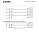
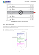
Table Of Contents
- 1. INTRODUCTION
- 2. INSTALLATION
- 3. SWITCH MANAGEMENT
- 4. WEB CONFIGURATION
- 4.1 Main Web page
- 4.2 System
- 4.2.1 System Information
- 4.2.2 IP Configuration
- 4.2.3 IP Status
- 4.2.4 Users Configuration
- 4.2.5 Privilege Levels
- 4.2.6 NTP Configuration
- 4.2.7 Time Configuration
- 4.2.8 UPnP
- 4.2.9 DHCP Relay
- 4.2.10 DHCP Relay Statistics
- 4.2.11 CPU Load
- 4.2.12 System Log
- 4.2.13 Detailed Log
- 4.2.14 Remote Syslog
- 4.2.15 SMTP Configuration
- 4.2.16 Web Firmware Upgrade
- 4.2.17 TFTP Firmware Upgrade
- 4.2.18 Save Startup Config
- 4.2.19 Configuration Download
- 4.2.20 Configuration Upload
- 4.2.21 Configuration Activate
- 4.2.22 Configuration Delete
- 4.2.23 Image Select
- 4.2.24 Factory Default
- 4.2.25 System Reboot
- 4.3 Simple Network Management Protocol
- 4.4 Port Management
- 4.5 Link Aggregation
- 4.6 VLAN
- 4.7 Spanning Tree Protocol
- 4.8 Multicast
- 4.8.1 IGMP Snooping
- 4.8.2 Profile Table
- 4.8.3 Address Entry
- 4.8.4 IGMP Snooping Configuration
- 4.8.5 IGMP Snooping VLAN Configuration
- 4.8.6 IGMP Snooping Port Group Filtering
- 4.8.7 IGMP Snooping Status
- 4.8.8 IGMP Group Information
- 4.8.9 IGMPv3 Information
- 4.8.10 MLD Snooping Configuration
- 4.8.11 MLD Snooping VLAN Configuration
- 4.8.12 MLD Snooping Port Group Filtering
- 4.8.13 MLD Snooping Status
- 4.8.14 MLD Group Information
- 4.8.15 MLDv2 Information
- 4.8.16 MVR (Multicast VLAN Registration)
- 4.8.17 MVR Status
- 4.8.18 MVR Groups Information
- 4.8.19 MVR SFM Information
- 4.9 Quality of Service
- 4.9.1 Understanding QoS
- 4.9.2 Port Policing
- 4.9.3 Port Classification
- 4.9.4 Port Scheduler
- 4.9.5 Port Shaping
- 4.9.6 Port Tag Remarking
- 4.9.7 Port DSCP
- 4.9.8 DSCP-based QoS
- 4.9.9 DSCP Translation
- 4.9.10 DSCP Classification
- 4.9.11 QoS Control List
- 4.9.12 QCL Status
- 4.9.13 Storm Control Configuration
- 4.9.14 WRED
- 4.9.15 QoS Statistics
- 4.9.16 Voice VLAN Configuration
- 4.9.17 Voice VLAN OUI Table
- 4.10 Access Control Lists
- 4.11 Authentication
- 4.11.1 Understanding IEEE 802.1X Port-Based Authentication
- 4.11.2 Authentication Configuration
- 4.11.3 Network Access Server Configuration
- 4.11.4 Network Access Overview
- 4.11.5 Network Access Statistics
- 4.11.6 RADIUS
- 4.11.7 TACACS+
- 4.11.8 RADIUS Overview
- 4.11.9 RADIUS Details
- 4.11.10 Windows Platform RADIUS Server Configuration
- 4.11.11 802.1X Client Configuration
- 4.12 Security
- 4.12.1 Port Limit Control
- 4.12.2 Access Management
- 4.12.3 Access Management Statistics
- 4.12.4 HTTPs
- 4.12.5 SSH
- 4.12.6 Port Security Status
- 4.12.7 Port Security Detail
- 4.12.8 DHCP Snooping
- 4.12.9 Snooping Table
- 4.12.10 IP Source Guard Configuration
- 4.12.11 IP Source Guard Static Table
- 4.12.12 ARP Inspection
- 4.12.13 ARP Inspection Static Table
- 4.13 Address Table
- 4.14 LLDP
- 4.15 Network Diagnostics
- 4.16 Power over Ethernet (SGS-5220-24P2X only)
- 4.17 Loop Protection
- 4.18 RMON
- 4.19 Stack
- 5. SWITCH OPERATION
- 6. TROUBLESHOOTING
- APPENDIX A: Networking Connection
- APPENDIX B : GLOSSARY
- EC Declaration of Conformity

User’s Manual of SGS-5220 Series
347
General Switch ID Assignment Rules
When assigning Switch IDs to the devices in the stack, you must note the following:
1. Switches with assigned IDs can be changed to use any other switch ID (possibly by swapping Switch ID with
another active switch).
2. When swapping two Switch IDs, the devices will retain their (own) configuration, except for the Switch ID.
3. Switches without an assigned Switch ID can only be assigned to any unused ID.
4. When assigning a Switch ID of an inactive switch to a new switch, the new switch will inherit the former's
configuration (see "Replacing a Switch" above).
5. Deleting a switch will remove any configuration pertaining to it.
6. Deleting an active switch will leave it with an unassigned Switch ID until rebooted or manually assigning a Switch
ID.
4.19.1.2 Master Selection
Within a managed stack, one master switch (or just "master") must be selected. Any switch not being master is a slave switch
(or just "slave").
To elect a master, the following criteria are evaluated sequentially:
1. If any switch already claims to have been master for more than 30 seconds, then that switch will become
master.
2. If multiple switches claim to have been master for more than 30 seconds, then the switch which has been
master for the longest period of time will become master.
3. The switch with the smallest master priority.
4. The switch with the smallest MAC address.
The above algorithm ensures that once a master has been selected and has been master for more than 30 seconds, it will
remain master. However in some cases the user may want to enforce a new master selection.
4.19.1.3 Stack Redundancy
In the unlikely event that a SGS-5220 Series Switch fails in a stack, stack integrity is maintained if the redundant cable is
connected to the stack. The affected switch within the sack can be replaced or removed without disrupting normal operation.
The broken link is bypassed and data transmission continues uninterrupted. The single management IP address for the stack is
also preserved for uninterrupted management and monitoring.