
SGS-5220 Series User Manual
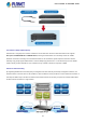

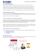
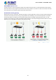
Table Of Contents
- 1. INTRODUCTION
- 2. INSTALLATION
- 3. SWITCH MANAGEMENT
- 4. WEB CONFIGURATION
- 4.1 Main Web page
- 4.2 System
- 4.2.1 System Information
- 4.2.2 IP Configuration
- 4.2.3 IP Status
- 4.2.4 Users Configuration
- 4.2.5 Privilege Levels
- 4.2.6 NTP Configuration
- 4.2.7 Time Configuration
- 4.2.8 UPnP
- 4.2.9 DHCP Relay
- 4.2.10 DHCP Relay Statistics
- 4.2.11 CPU Load
- 4.2.12 System Log
- 4.2.13 Detailed Log
- 4.2.14 Remote Syslog
- 4.2.15 SMTP Configuration
- 4.2.16 Web Firmware Upgrade
- 4.2.17 TFTP Firmware Upgrade
- 4.2.18 Save Startup Config
- 4.2.19 Configuration Download
- 4.2.20 Configuration Upload
- 4.2.21 Configuration Activate
- 4.2.22 Configuration Delete
- 4.2.23 Image Select
- 4.2.24 Factory Default
- 4.2.25 System Reboot
- 4.3 Simple Network Management Protocol
- 4.4 Port Management
- 4.5 Link Aggregation
- 4.6 VLAN
- 4.7 Spanning Tree Protocol
- 4.8 Multicast
- 4.8.1 IGMP Snooping
- 4.8.2 Profile Table
- 4.8.3 Address Entry
- 4.8.4 IGMP Snooping Configuration
- 4.8.5 IGMP Snooping VLAN Configuration
- 4.8.6 IGMP Snooping Port Group Filtering
- 4.8.7 IGMP Snooping Status
- 4.8.8 IGMP Group Information
- 4.8.9 IGMPv3 Information
- 4.8.10 MLD Snooping Configuration
- 4.8.11 MLD Snooping VLAN Configuration
- 4.8.12 MLD Snooping Port Group Filtering
- 4.8.13 MLD Snooping Status
- 4.8.14 MLD Group Information
- 4.8.15 MLDv2 Information
- 4.8.16 MVR (Multicast VLAN Registration)
- 4.8.17 MVR Status
- 4.8.18 MVR Groups Information
- 4.8.19 MVR SFM Information
- 4.9 Quality of Service
- 4.9.1 Understanding QoS
- 4.9.2 Port Policing
- 4.9.3 Port Classification
- 4.9.4 Port Scheduler
- 4.9.5 Port Shaping
- 4.9.6 Port Tag Remarking
- 4.9.7 Port DSCP
- 4.9.8 DSCP-based QoS
- 4.9.9 DSCP Translation
- 4.9.10 DSCP Classification
- 4.9.11 QoS Control List
- 4.9.12 QCL Status
- 4.9.13 Storm Control Configuration
- 4.9.14 WRED
- 4.9.15 QoS Statistics
- 4.9.16 Voice VLAN Configuration
- 4.9.17 Voice VLAN OUI Table
- 4.10 Access Control Lists
- 4.11 Authentication
- 4.11.1 Understanding IEEE 802.1X Port-Based Authentication
- 4.11.2 Authentication Configuration
- 4.11.3 Network Access Server Configuration
- 4.11.4 Network Access Overview
- 4.11.5 Network Access Statistics
- 4.11.6 RADIUS
- 4.11.7 TACACS+
- 4.11.8 RADIUS Overview
- 4.11.9 RADIUS Details
- 4.11.10 Windows Platform RADIUS Server Configuration
- 4.11.11 802.1X Client Configuration
- 4.12 Security
- 4.12.1 Port Limit Control
- 4.12.2 Access Management
- 4.12.3 Access Management Statistics
- 4.12.4 HTTPs
- 4.12.5 SSH
- 4.12.6 Port Security Status
- 4.12.7 Port Security Detail
- 4.12.8 DHCP Snooping
- 4.12.9 Snooping Table
- 4.12.10 IP Source Guard Configuration
- 4.12.11 IP Source Guard Static Table
- 4.12.12 ARP Inspection
- 4.12.13 ARP Inspection Static Table
- 4.13 Address Table
- 4.14 LLDP
- 4.15 Network Diagnostics
- 4.16 Power over Ethernet (SGS-5220-24P2X only)
- 4.17 Loop Protection
- 4.18 RMON
- 4.19 Stack
- 5. SWITCH OPERATION
- 6. TROUBLESHOOTING
- APPENDIX A: Networking Connection
- APPENDIX B : GLOSSARY
- EC Declaration of Conformity

User’s Manual of SGS-5220 Series
14
Flexible and Extendable Solution
The 4 mini-GBIC SFP slots built in the SGS-5220 switch series support dual speed as it features 100BASE-FX and
1000BASE-SX/LX SFP (Small Form-factor Pluggable) fiber-optic modules. Now the administrator can flexibly choose the
suitable SFP transceiver according to not only the transmission distance, but also the transmission speed required. The
distance can be extended from 550 meters to 2km (multi-mode fiber) and up to above 10/20/30/40/50/70/120 kilometers
(single-mode fiber or WDM fiber). They are well suited for applications within the enterprise data centers and distributions.
Intelligent SFP Diagnosis Mechanism
The SGS-5220 switch series supports SFP-DDM (Digital Diagnostic Monitor) function that greatly helps network administrator
to easily monitor real-time parameters of the SFP and SFP+ transceivers, such as optical output power, optical input power,
temperature, laser bias current, and transceiver supply voltage.
Centralized Power Management for Gigabit Ethernet PoE Networking
To fulfill the needs of higher power required PoE network applications with Gigabit speed transmission, the SGS-5220-24P2X
features high-performance Gigabit IEEE 802.3af PoE (up to 15.4 watts) and IEEE 802.3at PoE+ (up to 30 watts) on all ports. It
perfectly meets the power requirements of PoE VoIP phone and all kinds of PoE IP cameras such as IR, PTZ, speed dome
cameras or even box type IP cameras with built-in fan and heater for high power consumption.
The SGS-5220-24P2X’s PoE capabilities also help to reduce deployment costs for network devices as a result of freeing from
restrictions of power outlet locations. Power and data switching are integrated into one unit, delivered over a single cable and
managed centrally. It thus eliminates cost for additional AC wiring and reduces installation time.
Built-in Unique PoE Functions for Surveillance Management
As a managed PoE Switch for surveillance network, the SGS-5220-24P2X features intelligent PoE Management functions:
Scheduled Power Recycling
SMTP/SNMP Trap Event Alert
PoE Schedule
Scheduled Power Recycling
The SGS-5220-24P2X allows each of the connected PD (Powered Device) to reboot in a specific time each week. Therefore, it
will reduce the chance of PD (Powered Device) crash resulting from buffer overflow.