User’s Manual of SGS-5220 Series 1
User’s Manual of SGS-5220 Series Trademarks Copyright © PLANET Technology Corp. 2015. Contents are subject to revision without prior notice. PLANET is a registered trademark of PLANET Technology Corp. All other trademarks belong to their respective owners.
User’s Manual of SGS-5220 Series TABLE OF CONTENTS 1. INTRODUCTION .................................................................................................................. 10 1.1 Packet Contents ......................................................................................................................................... 10 1.2 Product Description ................................................................................................................................... 11 1.
User’s Manual of SGS-5220 Series 4.2 System ......................................................................................................................................................... 52 4.2.1 System Information.............................................................................................................................................. 53 4.2.2 IP Configuration ......................................................................................................................
User’s Manual of SGS-5220 Series 4.4.2 Port Statistics Overview ....................................................................................................................................... 95 4.4.3 Port Statistics Detail ............................................................................................................................................. 96 4.4.4 SFP Module Information ..........................................................................................................
User’s Manual of SGS-5220 Series 4.8.3 Address Entry .................................................................................................................................................... 160 4.8.4 IGMP Snooping Configuration ........................................................................................................................... 161 4.8.5 IGMP Snooping VLAN Configuration .........................................................................................................
User’s Manual of SGS-5220 Series 4.10.1 Access Control List Status ............................................................................................................................... 210 4.10.2 Access Control List Configuration .................................................................................................................... 212 4.10.3 ACE Configuration ..............................................................................................................................
User’s Manual of SGS-5220 Series 4.14.2 LLDP Configuration ......................................................................................................................................... 295 4.14.3 LLDP MED Configuration ................................................................................................................................ 298 4.14.4 LLDP-MED Neighbor ...........................................................................................................................
User’s Manual of SGS-5220 Series 4.19.3 Stack Information ............................................................................................................................................. 352 4.19.4 Stack Port State Overview ............................................................................................................................... 353 4.19.5 Stack Example ..........................................................................................................................
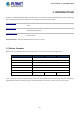
User’s Manual of SGS-5220 Series 1. INTRODUCTION PLANET L2+ Stackable Managed Switch, SGS-5220 series, comes with the multi-port Gigabit Ethernet Switch and SFP fiber optic connectibility and robust layer 2 features. The description of this model is shown below: SGS-5220-24T2X L2+ 24-Port 10/100/1000T + 4-Port Shared SFP + 2-Port 10G SFP+ Stackable Managed Switch SGS-5220-24P2X L2+ 24-Port 10/100/1000T 802.
User’s Manual of SGS-5220 Series 1.2 Product Description High-Density, Resilient Deployment Switch Solution for Gigabit Networking of Enterprise, Campus and Data Center For the growing Gigabit network and IoT (Internet of Things) demand, PLANET has launched a new-generation Stackable Gigabit Switch solution, the SGS-5220 switch series, to meet the needs of enterprises, telecoms and campuses for a large-scale network deployment.
User’s Manual of SGS-5220 Series Cost-effective 10Gbps Uplink Capacity 10G Ethernet is a big leap in the evolution of Ethernet. The two 10G SFP+ slot of the SGS-5220 switch series supports Dual-speed, 10GBASE-SR/LR or 1000BASE-SX/LX, meaning the administrator now can flexibly choose the suitable SFP/SFP+ transceiver according to the transmission distance or the transmission speed required to extend the network efficiently.
User’s Manual of SGS-5220 Series IPv4 and IPv6 VLAN Routing for Secure and Flexible Management To help customers stay on top of their businesses, the SGS-5220 switch series not only provides ultra high transmission performance and excellent layer 2 technologies, but also offers IPv4/IPv6 VLAN routing feature which allows to crossover different VLANs and different IP addresses for the purpose of having a highly secured, flexible management and simpler networking application.
User’s Manual of SGS-5220 Series Flexible and Extendable Solution The 4 mini-GBIC SFP slots built in the SGS-5220 switch series support dual speed as it features 100BASE-FX and 1000BASE-SX/LX SFP (Small Form-factor Pluggable) fiber-optic modules. Now the administrator can flexibly choose the suitable SFP transceiver according to not only the transmission distance, but also the transmission speed required.
User’s Manual of SGS-5220 Series SMTP/SNMP Trap Event alert Though most NVR or camera management softwares offer SMTP email alert function, the SGS-5220-24P2X further provides event alert function to help to diagnose the abnormal device owing to whether or not there is a break of the network connection, loss of PoE power or the rebooting response by PD Alive Check process.
User’s Manual of SGS-5220 Series 1.3 How to Use This Manual This User’s Manual is structured as follows: Section 2, INSTALLATION The section explains the functions of the Managed Switch and how to physically install the Managed Switch. Section 3, SWITCH MANAGEMENT The section contains the information about the software function of the Managed Switch. Section 4, WEB CONFIGURATION The section explains how to manage the Managed Switch by Web interface.
User’s Manual of SGS-5220 Series 1.4 Product Features Physical Port 24-Port 10/100/1000BASE-T RJ45 copper (SGS-5220-24T2X) 24-Port 10/100/1000BASE-T RJ45 copper with IEEE 802.3at / 802.
User’s Manual of SGS-5220 Series Layer 3 IP Routing Features Supports maximum 128 static routes and route summarization Quality of Service ■ Ingress Shaper and Egress Rate Limit per port bandwidth control ■ 8 priority queues on all switch ports ■ Traffic classification - IEEE 802.
User’s Manual of SGS-5220 Series Built-in Trivial File Transfer Protocol (TFTP) client BOOTP and DHCP for IP address assignment System Maintenance - Firmware upload and download via HTTP or TFTP - Reset button for system reboot or reset to factory default - Dual Images DHCP Relay DHCP Option82 User Privilege levels control NTP (Network Time Protocol) Link Layer Discovery Protocol (LLDP) and LLDP-MED Network Diagnostic - ICMPv6 and ICMPv4 Remote Ping - Cable Diagnostic technology p
User’s Manual of SGS-5220 Series 1.
User’s Manual of SGS-5220 Series Stacking Functions Stacking Ports 2 SFP+ slots Stacking Numbers 16 Stacking Bandwidth 40Gbps full duplex Stack ID Display 7-Segment LED display (1~9, A~F, 0) Stack Topology Ring/Chain/Back-to-Back Power over Ethernet PoE Standard - - IEEE 802.3at PoE / PSE PoE Power Supply Type - - End-span PoE Power Output - - Per Port 56V DC, Max. 30.8 watts Power Pin Assignment - - 1/2(+), 3/6(-) PoE Power Budget - - 440 watts (max.
User’s Manual of SGS-5220 Series - 802.1p priority - 802.
User’s Manual of SGS-5220 Series 2. INSTALLATION This section describes the hardware features and installation of the Managed Switch on the desktop or rack mount. For easier management and control of the Managed Switch, familiarize yourself with its display indicators, and ports. Front panel illustrations in this chapter display the unit LED indicators. Before connecting any network device to the Managed Switch, please read this chapter completely. 2.1 Hardware Description 2.1.
User’s Manual of SGS-5220 Series ■ 10 Gigabit SFP+ Slot 10GBASE-SR/LR mini-GBIC slot, SFP+ Transceiver Module supports from 300 meters (multi-mode fiber) to up to 10 kilometers (single-mode fiber) ■ 10 Gigabit Stacked SFP+ Slot 10GBASE-SR/LR mini-GBIC slot, SFP+ Transceiver Module supports from 300 meters (multi-mode fiber) to up to 10 kilometers (single-mode fiber) ■ Console Port The console port is an RJ45 port connector. It is an interface for connecting a terminal directly.
User’s Manual of SGS-5220 Series 2.1.2 LED Indications The front panel LEDs indicate instant status of power and system status, fan status, port links/PoE-in-use and data activity; they help monitor and troubleshoot when needed. Figure 2-1-2 and Figure 2-1-6 show the LED indications of the Managed Switch.
User’s Manual of SGS-5220 Series Per TP/SFP combo interface (Port-21 to Port-24) LED Color 1000 LNK/ACT Green 100 LNK/ACT Orange Function Lights to indicate the port is running in 1000Mbps speed and successfully established. Blinks to indicate that the switch is actively sending or receiving data over that port. Lights to indicate the port is running in 10/100Mbps speed and successfully established. Blinks to indicate that the switch is actively sending or receiving data over that port.
User’s Manual of SGS-5220 Series PWR1 Green Lights to indicate power supply 1 has failed. PWR2 Green Lights to indicate power supply 2 has failed. Lights to indicate the link through that SFP+ stacking port is successfully established with STX1 Green speed 10Gbps. Off to indicate that the port is link down. Lights to indicate the link through that SFP+ stacking port is successfully established with STX2 Green speed 10Gbps. Off to indicate that the port is link down.
User’s Manual of SGS-5220 Series SGS-5220-24S2XR LED Indication Table LED definition System/Stack LED Color PWR Green Function Lights to indicate that the Switch is powered on. Blinks to indicate the System is running under booting procedure. Master Green Lights to indicate that the Switch is the Master of the stack group. Lights to indicate the link through that SFP+ stacking port is successfully established with STX1 Green speed 10Gbps. Off to indicate that the port is link down.
User’s Manual of SGS-5220 Series 2.1.3 Switch Rear Panel The rear panel of the Managed Switch indicates an AC inlet power socket, which accepts input power from 100 to 240V AC, 50-60Hz. Figures 2-1-4A, 2-1-4B and 2-1-4C show the rear panel of the Managed Switch.
User’s Manual of SGS-5220 Series ■ DC Power Connector The rear panel of the SGS-5220-24S2XR contains a power switch and a DC power connector, which accepts DC power input voltage from 36V to 60V DC. Connect the power cable to the Managed Switch at the input terminal block. The size of the two screws in the terminal block is M3.5.
User’s Manual of SGS-5220 Series 2.2 Installing the Managed Switch This section describes how to install your Managed Switch and make connections to the Managed Switch. Please read the following topics and perform the procedures in the order being presented. To install your Managed Switch on a desktop or shelf, simply complete the following steps. 2.2.
User’s Manual of SGS-5220 Series 2.2.2 Rack Mounting To install the Managed Switch in a 19-inch standard rack, please follow the instructions described below. Step 1: Place the Managed Switch on a hard flat surface, with the front panel positioned towards the front side. Step 2: Attach the rack-mount bracket to each side of the Managed Switch with supplied screws attached to the package. Figure 2-2-2 shows how to attach brackets to one side of the Managed Switch.
User’s Manual of SGS-5220 Series Step 6: Proceed with Steps 4 and 5 of session 2.2.1 Desktop Installation to connect the network cabling and supply power to the Managed Switch. 2.2.3 Installing the SFP/SFP+ Transceiver The sections describe how to insert an SFP/SFP+ transceiver into an SFP/SFP+ slot. The SFP/SFP+ transceivers are hot-pluggable and hot-swappable. You can plug in and out the transceiver to/from any SFP/SFP+ port without having to power down the Managed Switch, as the Figure 2-2-4 shows..
User’s Manual of SGS-5220 Series MFB-FB20 100 WDM(LC) Single Mode 20km 1550nm/1310nm 0 ~ 60 degrees C MFB-TFA20 100 WDM(LC) Single Mode 20km 1310nm/1550nm -40 ~ 75 degrees C MFB-TFB20 100 WDM(LC) Single Mode 20km 1550nm/1310nm -40 ~ 75 degrees C MFB-TFA40 100 WDM(LC) Single Mode 40km 1310nm/1550nm -40 ~ 75 degrees C MFB-TFB40 100 WDM(LC) Single Mode 40km 1550nm/1310nm -40 ~ 75 degrees C Gigabit Ethernet Transceiver (1000BASE-X SFP) Model Speed (Mbps) Connector Interface
User’s Manual of SGS-5220 Series 10Gbps SFP+ (10G Ethernet/10GBASE) Model Speed (Mbps) Connector Interface Fiber Mode Distance MTB-SR 10G LC Multi Mode Up to 300m 850nm 0 ~ 60 degrees C MTB-LR 10G LC Single Mode 10km 1310nm 0 ~ 60 degrees C Wavelength (nm) Operating Temp.
User’s Manual of SGS-5220 Series 3. Lift up the lever of the MGB module and turn it to a horizontal position. 4. Pull out the module gently through the lever. Figure 2-2-5: How to Pull Out the SFP/SFP+ Transceiver Never pull out the module without lifting up the lever of the module and turning it to a horizontal position. Directly pulling out the module could damage the module and the SFP/SFP+ module slot of the Managed Switch.
User’s Manual of SGS-5220 Series 2.3 Stack Installation SGS-5220 Series The SGS-5220 managed switch series provides a switch stacking function to manage up to 16 switches using a single IP address. And up to 384 Gigabit Ethernet ports and 32 high-capacity 10G SFP+ ports can be managed by a stacking group and you can add ports and functionality as needed.
User’s Manual of SGS-5220 Series 2.3.1 Connecting Stacking Cable Before attempting to connect stacking ports, verify that you have the required stack cables. The following cables are used to connect stacked switches: • CB-DASFP-0.5M: 10G SFP+ Directly-attached Copper Cable (0.5M in length) • CB-DASFP-2M: 10G SFP+ Directly-attached Copper Cable (2M in length) • MTB-LR: SFP+ Port 10GBASE-LR mini-GBIC Module (single-mode/1310nm/max. 10km). • MTB-SR: SFP+ Port 10GBASE-SR mini-GBIC Module (multi-mode/850nm/max.
User’s Manual of SGS-5220 Series 2.3.2 Management Stacking The stack operation of the SGS Managed Switch supports Plug and Play Stacking connection and auto stack configuration. Step 5: Once the stack starts operation, the Stack master will be automatically selected without any configuration. The Stack master is indicated by a lit green “Master” LED on the front panel as Figure 2-24 shows.
User’s Manual of SGS-5220 Series Figure 2-25 Use PLANET Smart Discovery Utility to display the IP address of stack master 1. The stack switch with the least priority ID or MAC Address number will become Master. Only Master switch’s management interface (console, Telnet, Web and SNMP) is accessible. It allows to build a stack of up to 16 PLANET SGS Switches.
User’s Manual of SGS-5220 Series 3. SWITCH MANAGEMENT This chapter explains the methods that you can use to configure management access to the Managed Switch. It describes the types of management applications and the communication and management protocols that deliver data between your management device (workstation or personal computer) and the system. It also contains information about port connection options.
User’s Manual of SGS-5220 Series 3.2 Management Access Overview The Managed Switch gives you the flexibility to access and manage it using any or all of the following methods: An administration console Web browser interface An external SNMP-based network management application The administration console and Web browser interface support are embedded in the Managed Switch software and are available for immediate use. Each of these management methods has their own advantages.
User’s Manual of SGS-5220 Series 3.3 Administration Console The administration console is an internal, character-oriented, and command line user interface for performing system administration such as displaying statistics or changing option settings. Using this method, you can view the administration console from a terminal, personal computer, Apple Macintosh, or workstation connected to the Managed Switch's console (serial) port.
User’s Manual of SGS-5220 Series You can change these settings, if desired, after you log on. This management method is often preferred because you can remain connected and monitor the system during system reboots. Also, certain error messages are sent to the serial port, regardless of the interface through which the associated action was initiated. A Macintosh or PC attachment can use any terminal-emulation program for connecting to the terminal serial port.
User’s Manual of SGS-5220 Series 3.4 Web Management The Managed Switch offers management features that allow users to manage the Managed Switch from anywhere on the network through a standard browser such as Microsoft Internet Explorer. After you set up your IP address for the switch, you can access the Managed Switch's Web interface applications directly in your Web browser by entering the IP address of the Managed Switch.
User’s Manual of SGS-5220 Series 3.5 SNMP-based Network Management You can use an external SNMP-based application to configure and manage the Managed Switch, such as SNMP Network Manager, HP Openview Network Node Management (NNM) or What’s Up Gold. This management method requires the SNMP agent on the switch and the SNMP Network Management Station to use the same community string. This management method, in fact, uses two community strings: the get community string and the set community string.
User’s Manual of SGS-5220 Series If there are two LAN cards or above in the same administrator PC, choose a different LAN card by using the “Select Adapter” tool. 3. Press the “Refresh” button for the currently connected devices in the discovery list as the screen shows below: Figure 3-1-7: Planet Smart Discovery Utility Screen 1. This utility shows all necessary information from the devices, such as MAC Address, Device Name, firmware version, and Device IP Subnet address.
User’s Manual of SGS-5220 Series 4. WEB CONFIGURATION This section introduces the configuration and functions of the Web-based management from Managed Switch. About Web-based Management The Managed Switch offers management features that allow users to manage the Managed Switch from anywhere on the network through a standard browser such as Microsoft Internet Explorer. The Web-based Management supports Internet Explorer 7.0.
User’s Manual of SGS-5220 Series username/password you have changed via console) to login the main screen of Managed Switch. The login screen in Figure 4-1-2 appears. Figure 4-1-2: Login Screen Default User name: admin Default Password: admin After entering the username and password, the main screen appears in Figure 4-1-3. Figure 4-1-3: Web Main ppage Now, you can use the Web management interface to continue the switch management or manage the Managed Switch by Web interface.
User’s Manual of SGS-5220 Series 1. It is recommended to use Internet Explore 7.0 or above to access Managed Switch. 2. The changed IP address takes effect immediately after clicking on the Save button. You need to use the new IP address to access the Web interface. 3. For security reason, please change and memorize the new password after this first setup. 4. Only accept command in lowercase letter under web interface. 4.
User’s Manual of SGS-5220 Series Main Menu Using the onboard web agent, you can define system parameters, manage and control the Managed Switch, and all its ports, or monitor network conditions. Via the Web-Management, the administrator can set up the Managed Switch by selecting the functions those listed in the Main Function. The screen in Figure 4-1-5 appears.
User’s Manual of SGS-5220 Series 4.2 System Use the System menu items to display and configure basic administrative details of the Managed Switch. Under the System, the following topics are provided to configure and view the system information. This section has the following items: ■ System Information The Managed Switch system information is provided here. ■ IP Configuration Configures the Managed Switch-managed IPv4/IPv6 interface and IP routes on this page.
User’s Manual of SGS-5220 Series 4.2.1 System Information The System Infomation page provides information for the current device information. System Information page helps a switch administrator to identify the hardware MAC address, software version and system uptime. The screen in Figure 4-2-1 appears. Figure 4-2-1: System Information page Screenshot The page includes the following fields: Object Description • Contact The system contact configured in SNMP | System Information | System Contact.
User’s Manual of SGS-5220 Series 4.2.2 IP Configuration The IP Configuration includes the IP Configuration, IP Interface and IP Routes. The configured column is used to view or change the IP configuration. The maximum number of interfaces supported is 128 and the maximum number of routes is 32. The screen in Figure 4-2-2 appears. Figure 4-2-2: IP Configuration page Screenshot The current column is used to show the active IP configuration.
User’s Manual of SGS-5220 Series Specify from which DHCP-enabled interface a provided DNS server should be preferred. DNS Proxy When DNS proxy is enabled, system will relay DNS requests to the currently configured DNS server, and reply as a DNS resolver to the client devices on the network. • IP Address Delete Select this option to delete an existing IP interface. VLAN The VLAN associated with the IP interface. Only ports in this VLAN will be able to access the IP interface.
User’s Manual of SGS-5220 Series 4.2.3 IP Status IP Status displays the status of the IP protocol layer. The status is defined by the IP interfaces, the IP routes and the neighbour cache (ARP cache) status. The screen in Figure 4-2-3 appears. Figure 4-2-3: IP Status page Screenshot The page includes the following fields: Object Description • IP Interfaces • IP Routes • Neighbor Cache Interface The name of the interface. Type The address type of the entry. This may be LINK or IPv4.
User’s Manual of SGS-5220 Series 4.2.4 Users Configuration This page provides an overview of the current users. Currently the only way to login as another user on the web server is to close and reopen the browser. After setup is completed, press the “Apply” button to take effect. Please login web interface with a new user name and password as Figure 4-2-4 shows.
User’s Manual of SGS-5220 Series Figure 4-2-5: Add/Edit User Configuration page Screenshot The page includes the following fields: Object Description • Username A string identifying the user name that this entry should belong to. The allowed string length is 1 to 31. The valid user name is a combination of letters, numbers and underscores. • Password The password of the user. The allowed string length is 1 to 31. • Password (again) Please enter the user’s new password here again to confirm.
User’s Manual of SGS-5220 Series Generally, the privilege level 15 can be used for an administrator account, privilege level 10 for a standard user account and privilege level 5 for a guest account. Once the new user is added, the new user entry shown on the Users Configuration page.
User’s Manual of SGS-5220 Series 4.2.5 Privilege Levels This page provides an overview of the privilege levels. After setup is completed, please press the “Apply” button to take effect. Please login web interface with the new user name and password and the screen in Figure 4-2-7 appears.
User’s Manual of SGS-5220 Series • Group Name The name identifying the privilege group. In most cases, a privilege level group consists of a single module (e.g., LACP, RSTP or QoS), but a few of them contain more than one. The following description defines these privilege level groups in details: System: Contact, Name, Location, Timezone, Log.
User’s Manual of SGS-5220 Series 4.2.6 NTP Configuration Configure NTP on this page. NTP is an acronym for Network Time Protocol, a network protocol for synchronizing the clocks of computer systems. NTP uses UDP (data grams) as transport layer. You can specify NTP Servers. The NTP Configuration screen in Figure 4-2-8 appears. Figure 4-2-8: NTP Configuration page Screenshot The page includes the following fields: Object Description • Mode Indicates the NTP mode operation.
User’s Manual of SGS-5220 Series 4.2.7 Time Configuration Configure Time Zone on this page. A Time Zone is a region that has a uniform standard time for legal, commercial, and social purposes. It is convenient for areas in close commercial or other communication to keep the same time, so time zones tend to follow the boundaries of countries and their subdivisions.
User’s Manual of SGS-5220 Series Daylight Saving Time duration to repeat the configuration every year. Select 'Non-Recurring' and configure the Daylight Saving Time duration for single time configuration. ( Default : Disabled ). • Start Time Settings • Week - Select the starting week number. • Day - Select the starting day. • Month - Select the starting month. • Hours - Select the starting hour. • Minutes - Select the starting minute. • End Time Settings • Week - Select the ending week number.
User’s Manual of SGS-5220 Series Object Description • Mode Indicates the UPnP operation mode. Possible modes are: Enabled: Enable UPnP mode operation. Disabled: Disable UPnP mode operation. When the mode is enabled, two ACEs are added automatically to trap UPnP related packets to CPU. The ACEs are automatically removed when the mode is disabled. • TTL The TTL value is used by UPnP to send SSDP advertisement messages. Valid values are in the range of 1 to 255.
User’s Manual of SGS-5220 Series 4.2.9 DHCP Relay Configure DHCP Relay on this page. DHCP Relay is used to forward and to transfer DHCP messages between the clients and the server when they are not on the same subnet domain. The DHCP option 82 enables a DHCP relay agent to insert specific information into a DHCP request packets when forwarding client DHCP packets to a DHCP server and remove the specific information from a DHCP reply packets when forwarding server DHCP packets to a DHCP client.
User’s Manual of SGS-5220 Series they are not on the same subnet domain. • Relay Information Indicates the DHCP relay information mode option operation. Possible modes Mode are: Enabled: Enable DHCP relay information mode operation. When enabling DHCP relay information mode operation, the agent inserts specific information (option82) into a DHCP message when forwarding to DHCP server and removing it from a DHCP message when transferring to DHCP client.
User’s Manual of SGS-5220 Series The page includes the following fields: Server Statistics Object Description • Transmit to Server The packets number that relayed from client to server. • Transmit Error The packets number that errors sending packets to clients. • Receive from Server The packets number that received packets from server. • Receive Missing Agent The packets number that received packets without agent information options.
User’s Manual of SGS-5220 Series 4.2.11 CPU Load This page displays the CPU load, using a SVG graph. The load is measured as average over the last 100ms, 1sec and 10 seconds intervals. The last 120 samles are graphed, and the last numbers are displayed as text as well. In order to display the SVG graph, your browser must support the SVG format. Consult the SVG Wiki for more information on browser support.
User’s Manual of SGS-5220 Series 4.2.12 System Log The Managed Switch system log information is provided here. The System Log screen in Figure 4-2-15 appears. Figure 4-2-15: System Log page Screenshot The page includes the following fields: Object Description • ID The ID (>= 1) of the system log entry. • Level The level of the system log entry. The following level types are supported: Info: Information level of the system log. Warning: Warning level of the system log.
User’s Manual of SGS-5220 Series : Updates the system log entries, starting from the first available entry ID. : Updates the system log entries, ending at the last entry currently displayed. : Updates the system log entries, starting from the last entry currently displayed. : Updates the system log entries, ending at the last available entry ID. 4.2.13 Detailed Log The Managed Switch system detailed log information is provided here. The Detailed Log screen in Figure 4-2-16 appears.
User’s Manual of SGS-5220 Series 4.2.14 Remote Syslog Configure remote syslog on this page. The Remote Syslog screen in Figure 4-2-17 appears. Figure 4-2-17: Remote Syslog page Screenshot The page includes the following fields: Object Description • Mode Indicates the server mode operation. When the mode operation is enabled, the syslog message will send out to syslog server.
User’s Manual of SGS-5220 Series 4.2.15 SMTP Configuration This page facilitates an SMTP Configuration on the switch. The SMTP Configure screen in Figure 4-2-18 appears. Figure 4-2-18: SMTP Configuration page Screenshot The page includes the following fields: Object Description • SMTP Mode Controls whether SMTP is enabled on this switch. • SMTP Server Type the SMTP server name or the IP address of the SMTP server. • SMTP Port Set port number of SMTP service.
User’s Manual of SGS-5220 Series 4.2.16 Web Firmware Upgrade This page facilitates an update of the firmware controlling the switch. The Web Firmware Upgrade screen in Figure 4-2-19 appears. Figure 4-2-19: Web Firmware Upgrade page Screenshot To open Firmware Upgrade screen, perform the following: 1. Click System -> Web Firmware Upgrade. 2. The Firmware Upgrade screen is displayed as in Figure 4-2-19. 3. Click the “ 4. Select on the firmware then click “ 5.
User’s Manual of SGS-5220 Series 4.2.17 TFTP Firmware Upgrade The Firmware Upgrade page provides the functions to allow a user to update the Managed Switch firmware from the TFTP server in the network. Before updating, make sure you have your TFTP server ready and the firmware image is on the TFTP server. The TFTP Firmware Upgrade screen in Figure 4-2-21 appears.
User’s Manual of SGS-5220 Series 4.2.18 Save Startup Config This function allows save the current configuration, thereby ensuring that the current active configuration can be used at the next reboot screen in Figure 4-2-22 appears. After saving the configuratioin, the screen Figure 4-2-23 will appear. Figure 4-2-22: Configuration Save page Screenshot Figure 4-2-23: Finish Saving page Screenshot 4.2.19 Configuration Download The switch stores its configuration in a number of text files in CLI format.
User’s Manual of SGS-5220 Series 4.2.20 Configuration Upload Configuration Upload page allows the upload the running-config and startup-config on the switch. Please refer to the Figure 4-2-25 shown below. Figure 4-2-25: Configuration Upload page Screenshot If the destination is running-config, the file will be applied to the switch configuration. This can be done in two ways: • Replace mode: The current configuration is fully replaced with the configuration in the uploaded file.
User’s Manual of SGS-5220 Series It is possible to activate any of the configuration files present on the switch, except for running-config which represents the currently active configuration. Select the file to activate and click . This will initiate the process of completely replacing the existing configuration with that of the selected file. 4.2.22 Configuration Delete Configuration Delete page allows to delete the startup-config and default-config files which stored in FLASH.
User’s Manual of SGS-5220 Series Figure 4-2-28: Software Image Selection page Screenshot The page includes the following fields: Object Description • Image The flash index name of the firmware image. The name of primary (preferred) image is image, the alternate image is named image.bk. • Version The version of the firmware image. • Date The date where the firmware was produced. Buttons : Click to use the alternate image. This button may be disabled depending on system state. 4.2.
User’s Manual of SGS-5220 Series Buttons : Click to reset the configuration to Factory Defaults. : Click to return to the Port State page without resetting the configuration. To reset the Managed Switch to the Factory default setting, you can also press the hardware reset button at the front panel about 10 seconds. After the device be rebooted. You can login the management WEB interface within the same subnet of 192.168.0.xx. 4.2.
User’s Manual of SGS-5220 Series 4.3 Simple Network Management Protocol 4.3.1 SNMP Overview The Simple Network Management Protocol (SNMP) is an application layer protocol that facilitates the exchange of management information between network devices. It is part of the Transmission Control Protocol/Internet Protocol (TCP/IP) protocol suite. SNMP enables network administrators to manage network performance, find and solve network problems, and plan for network growth.
User’s Manual of SGS-5220 Series SNMP community An SNMP community is the group that devices and management stations running SNMP belong to. It helps define where information is sent. The community name is used to identify the group. A SNMP device or agent may belong to more than one SNMP community. It will not respond to requests from management stations that do not belong to one of its communities.
User’s Manual of SGS-5220 Series SNMP v2c: Set SNMP supported version 2c. SNMP v3: Set SNMP supported version 3. • Read Community Indicates the community read access string to permit access to SNMP agent. The allowed string length is 0 to 255, and the allowed content is the ASCII characters from 33 to 126. The field is applicable only when SNMP version is SNMPv1 or SNMPv2c. If SNMP version is SNMPv3, the community string will be associated with SNMPv3 communities table.
User’s Manual of SGS-5220 Series 4.3.3 SNMP Trap Configuration Configure SNMP trap on this page. The SNMP Trap Configuration screen in Figure 4-3-2 appears. Figure 4-3-2: SNMP Trap Configuration page Screenshot The page includes the following fields: Object Description • Trap Config Indicates which trap Configuration's name for configuring. The allowed string length is 0 to 255, and the allowed content is ASCII characters from 33 to 126. • Trap Mode Indicates the SNMP trap mode operation.
User’s Manual of SGS-5220 Series SNMP v1: Set SNMP trap supported version 1. SNMP v2c: Set SNMP trap supported version 2c. SNMP v3: Set SNMP trap supported version 3. • Trap Community Indicates the community access string when send SNMP trap packet. The allowed string length is 0 to 255, and the allowed content is the ASCII characters from 33 to 126. • Trap Destination Indicates the SNMP trap destination address. Address • Trap Destination Port Indicates the SNMP trap destination port.
User’s Manual of SGS-5220 Series • Switch Indicates that the Switch group's traps. Possible traps are: STP: Enable/disable STP trap. RMON: Enable/disable RMON trap. Buttons : Click to apply changes : Click to undo any changes made locally and revert to previously saved values. 4.3.4 SNMP System Information The switch system information is provided here. The SNMP System Information screen in Figure 4-3-3 appears.
User’s Manual of SGS-5220 Series 4.3.5 SNMPv3 Configuration 4.3.5.1 SNMPv3 Communities Configure SNMPv3 communities table on this page. The entry index key is Community. The SNMPv3 Communities screen in Figure 4-3-4 appears. Figure 4-3-4: SNMPv3 Communities Configuration page Screenshot The page includes the following fields: Object Description • Delete Check to delete the entry. It will be deleted during the next save.
User’s Manual of SGS-5220 Series 4.3.5.2 SNMPv3 Users Configure SNMPv3 users table on this page. The entry index keys are Engine ID and User Name. The SNMPv3 Users screen in Figure 4-3-5 appears. Figure 4-3-5: SNMPv3 Users Configuration page Screenshot The page includes the following fields: Object Description • Delete Check to delete the entry. It will be deleted during the next save. • Engine ID An octet string identifying the engine ID that this entry should belong to.
User’s Manual of SGS-5220 Series MD5: An optional flag to indicate that this user using MD5 authentication protocol. SHA: An optional flag to indicate that this user using SHA authentication protocol. The value of security level cannot be modified if entry already exist. That means must first ensure that the value is set correctly. • Authentication A string identifying the authentication pass phrase. For MD5 authentication Password protocol, the allowed string length is 8 to 32.
User’s Manual of SGS-5220 Series The page includes the following fields: Object Description • Delete Check to delete the entry. It will be deleted during the next save. • Security Model Indicates the security model that this entry should belong to. Possible security models are: v1: Reserved for SNMPv1. v2c: Reserved for SNMPv2c. usm: User-based Security Model (USM). • Security Name A string identifying the security name that this entry should belong to.
User’s Manual of SGS-5220 Series • View Name A string identifying the view name that this entry should belong to. The allowed string length is 1 to 32, and the allowed content is the ASCII characters from 33 to 126. • View Type Indicates the view type that this entry should belong to. Possible view type are: included: An optional flag to indicate that this view subtree should be included. excluded: An optional flag to indicate that this view subtree should be excluded.
User’s Manual of SGS-5220 Series string length is 1 to 32, and the allowed content is the ASCII characters from 33 to 126. • Security Model Indicates the security model that this entry should belong to. Possible security models are: any: Accepted any security model (v1|v2c|usm). v1: Reserved for SNMPv1. v2c: Reserved for SNMPv2c. usm: User-based Security Model (USM) • Security Level Indicates the security model that this entry should belong to.
User’s Manual of SGS-5220 Series 4.4 Port Management Use the Port Menu to display or configure the Managed Switch's ports. This section has the following items: Port Configuration Configures port connection settings Port Statistics Overview Lists Ethernet and RMON port statistics Port Statistics Detail Lists Ethernet and RMON port statistics SFP Module Information Display SFP information Port Mirror Sets the source and target ports for mirroring 4.4.
User’s Manual of SGS-5220 Series • Current Link Speed Provides the current link speed of the port. • Configured Link Speed Select any available link speed for the given switch port. Draw the menu bar to select the mode. Auto - Setup Auto negotiation for copper interface. 10Mbps HDX - Force sets 10Mbps/Half-Duplex mode. 10Mbps FDX - Force sets 10Mbps/Full-Duplex mode. 100Mbps HDX - Force sets 100Mbps/Half-Duplex mode. 100Mbps FDX - Force sets 100Mbps/Full-Duplex mode.
User’s Manual of SGS-5220 Series 4.4.2 Port Statistics Overview This page provides an overview of general traffic statistics for all switch ports. The Port Statistics Overview screen in Figure 4-4-2 appears. Figure 4-4-2: Port Statistics Overview page Screenshot The displayed counters are: Object Description • Port The logical port for the settings contained in the same row. • Packets The number of received and transmitted packets per port.
User’s Manual of SGS-5220 Series 4.4.3 Port Statistics Detail This page provides detailed traffic statistics for a specific switch port. Use the port select box to select which switch port details to display. The selected port belong to the currently selected stack unit, as reflected by the page header. The displayed counters are the totals for receive and transmit, the size counters for receive and transmit, and the error counters for receive and transmit.
User’s Manual of SGS-5220 Series Receive and Transmit Size Counters The number of received and transmitted (good and bad) packets split into categories based on their respective frame sizes. Receive and Transmit Queue Counters The number of received and transmitted packets per input and output queue. Receive Error Counters Object Description • Rx Drops The number of frames dropped due to lack of receive buffers or egress congestion.
User’s Manual of SGS-5220 Series 4.4.4 SFP Module Information The WGSW-48040HP has supported the SFP module with digital diagnostics monitoring (DDM) function, this feature is also known as digital optical monitoring (DOM). You can check the physical or operational status of an SFP module via the SFP Module Information page.
User’s Manual of SGS-5220 Series • Voltage(V) Display the voltage of current SFP DDM module, the voltage value is get from the – SFP DDM Module Only SFP DDM module. • Current(mA) Display the Ampere of current SFP DDM module, the Ampere value is get from – SFP DDM Module Only the SFP DDM module. • TX power(dBm) Display the TX power of current SFP DDM module, the TX power value is get – SFP DDM Module Only from the SFP DDM module.
User’s Manual of SGS-5220 Series Figure 4-4-7: Port Mirror Application The traffic to be copied to the mirror port is selected as follows: • All frames received on a given port (also known as ingress or source mirroring). • All frames transmitted on a given port (also known as egress or destination mirroring). Mirror Port Configuration The Port Mirror screen in Figure 4-4-8 appears.
User’s Manual of SGS-5220 Series • Port The logical port for the settings contained in the same row. • Mode Select mirror mode. ■ Rx only: Frames received at this port are mirrored to the mirroring port. Frames transmitted are not mirrored. ■ Tx only: Frames transmitted from this port are mirrored to the mirroring port. Frames received are not mirrored. ■ Disabled: Neither frames transmitted or frames received are mirrored.
User’s Manual of SGS-5220 Series 4.5 Link Aggregation Port Aggregation optimizes port usage by linking a group of ports together to form a single Link Aggregated Groups (LAGs). Port Aggregation multiplies the bandwidth between the devices, increases port flexibility, and provides link redundancy. Each LAG is composed of ports of the same speed, set to full-duplex operations. Ports in a LAG, can be of different media types (UTP/Fiber, or different fiber types), provided they operate at the same speed.
User’s Manual of SGS-5220 Series The Link Aggregation Control Protocol (LACP) provides a standardized means for exchanging information between Partner Systems that require high speed redundant links. Link aggregation lets you group up to eight consecutive ports into a single dedicated connection. This feature can expand bandwidth to a device on the network. LACP operation requires full-duplex mode, more detail information refer to the IEEE 802.3ad standard.
User’s Manual of SGS-5220 Series 4.5.1 Static Aggregation This page is used to configure the Aggregation hash mode and the aggregation group. The aggregation hash mode settings are global, whereas the aggregation group relate to the currently selected stack unit, as reflected by the page header. Hash Code Contributors The Static Aggregation screen in Figure 4-5-2 appears.
User’s Manual of SGS-5220 Series Figure 4-5-3: Aggregation Group Configuration page Screenshot The page includes the following fields: .Object Description • Group ID Indicates the group ID for the settings contained in the same row. Group ID "Normal" indicates there is no aggregation. Only one group ID is valid per port. • Port Members Each switch port is listed for each group ID.
User’s Manual of SGS-5220 Series settings relate to the currently selected stack unit, as reflected by the page header. The LACP Configuration screen in Figure 4-5-4 appears. Figure 4-5-4 : LACP Port Configuration page Screenshot The page includes the following fields: Object Description • Port The switch port number. • LACP Enabled Controls whether LACP is enabled on this switch port. LACP will form an aggregation when 2 or more ports are connected to the same partner.
User’s Manual of SGS-5220 Series which ports will be active and which ports will be in a backup role. Lower number means greater priority. Buttons : Click to apply changes : Click to undo any changes made locally and revert to previously saved values. 4.5.3 LACP System Status This page provides a status overview for all LACP instances. The LACP Status page display the current LACP aggregation Groups and LACP Port status. The LACP System Status screen in Figure 4-5-5 appears.
User’s Manual of SGS-5220 Series 4.5.4 LACP Port Status This page provides a status overview for LACP status for all ports. The LACP Port Status screen in Figure 4-5-6 appears. Figure 4-5-6: LACP Status page Screenshot The page includes the following fields: Object Description • Port The switch port number. • LACP 'Yes' means that LACP is enabled and the port link is up. 'No' means that LACP is not enabled or that the port link is down.
User’s Manual of SGS-5220 Series 4.5.5 LACP Port Statistics This page provides an overview for LACP statistics for all ports. The LACP Port Statistics screen in Figure 4-5-7 appears. Figure 4-5-7: LACP Statistics page Screenshot The page includes the following fields: Object Description • Port The switch port number. • LACP Received Shows how many LACP frames have been sent from each port. • LACP Transmitted Shows how many LACP frames have been received at each port.
User’s Manual of SGS-5220 Series 4.6 VLAN 4.6.1 VLAN Overview A Virtual Local Area Network (VLAN) is a network topology configured according to a logical scheme rather than the physical layout. VLAN can be used to combine any collection of LAN segments into an autonomous user group that appears as a single LAN. VLAN also logically segment the network into different broadcast domains so that packets are forwarded only between ports within the VLAN.
User’s Manual of SGS-5220 Series 4.6.2 IEEE 802.1Q VLAN In large networks, routers are used to isolate broadcast traffic for each subnet into separate domains. This Managed Switch provides a similar service at Layer 2 by using VLANs to organize any group of network nodes into separate broadcast domains. VLANs confine broadcast traffic to the originating group, and can eliminate broadcast storms in large networks. This also provides a more secure and cleaner network environment. An IEEE 802.
User’s Manual of SGS-5220 Series ■ 802.1Q VLAN Tags The figure below shows the 802.1Q VLAN tag. There are four additional octets inserted after the source MAC address. Their presence is indicated by a value of 0x8100 in the Ether Type field. When a packet's Ether Type field is equal to 0x8100, the packet carries the IEEE 802.1Q/802.1p tag.
User’s Manual of SGS-5220 Series Every physical port on a switch has a PVID. 802.1Q ports are also assigned a PVID, for use within the switch. If no VLAN are defined on the switch, all ports are then assigned to a default VLAN with a PVID equal to 1. Untagged packets are assigned the PVID of the port on which they were received. Forwarding decisions are based upon this PVID, in so far as VLAN are concerned. Tagged packets are forwarded according to the VID contained within the tag.
User’s Manual of SGS-5220 Series ■ Port Overlapping Port overlapping can be used to allow access to commonly shared network resources among different VLAN groups, such as file servers or printers. Note that if you implement VLANs which do not overlap, but still need to communicate, you can connect them by enabled routing on this switch. ■ Untagged VLANs Untagged (or static) VLANs are typically used to reduce broadcast traffic and to increase security.
User’s Manual of SGS-5220 Series ■ IEEE 802.1Q Tunneling (Q-in-Q) IEEE 802.1Q Tunneling (QinQ) is designed for service providers carrying traffic for multiple customers across their networks. QinQ tunneling is used to maintain customer-specific VLAN and Layer 2 protocol configurations even when different customers use the same internal VLAN IDs.
User’s Manual of SGS-5220 Series Global VLAN Configuration The Global VLAN Configuration screen in Figure 4-6-1 appears. Figure 4-6-1 : Global VLAN Configuration Screenshot The page includes the following fields: Object Description • Allowed Access This field shows the allowed Access VLANs, it only affects ports configured as VLANs Access ports. Ports in other modes are members of all VLANs specified in the Allowed VLANs field. By default, only VLAN 1 is enabled.
User’s Manual of SGS-5220 Series The page includes the following fields: Object Description • Port This is the logical port number for this row. • Mode Access Access ports are normally used to connect to end stations. Dynamic features like Voice VLAN may add the port to more VLANs behind the scenes.
User’s Manual of SGS-5220 Series The Port VLAN is called an "Access VLAN" for ports in Access mode and Native VLAN for ports in Trunk or Hybrid mode. • Port Type Ports in hybrid mode allow for changing the port type, that is, whether a frame's VLAN tag is used to classify the frame on ingress to a particular VLAN, and if so, which TPID it reacts on. Likewise, on egress, the Port Type determines the TPID of the tag, if a tag is required.
User’s Manual of SGS-5220 Series Only untagged frames are accepted on ingress. Tagged frames are discarded. Egress Tagging This option is only available for ports in Hybrid mode. Ports in Trunk and Hybrid mode may control the tagging of frames on egress. ■ Untag Port VLAN Frames classified to the Port VLAN are transmitted untagged. Other frames are transmitted with the relevant tag. ■ Tag All All frames, whether classified to the Port VLAN or not, are transmitted with a tag.
User’s Manual of SGS-5220 Series 4.6.4 VLAN Membership Status This page provides an overview of membership status for VLAN users. The VLAN Membership Status screen in Figure 4-6-4 appears. Figure 4-6-4: VLAN Membership Status for Static User page Screenshot The page includes the following fields: Object Description • VLAN User A VLAN User is a module that uses services of the VLAN management functionality to configure VLAN memberships and VLAN port configuration such as PVID, UVID.
User’s Manual of SGS-5220 Series information for all the VLAN Users, and this is by default. VLAN membership allows the frames classified to the VLAN ID to be forwarded on the respective VLAN member ports. Buttons : Select VLAN Users from this drop down list. Auto-refresh : Check this box to refresh the page automatically. Automatic refresh occurs every 3 seconds. : Click to refresh the page immediately. : Updates the table starting from the first entry in the VLAN Table, i.e.
User’s Manual of SGS-5220 Series tags are not removed. • Ingress Filtering Show the ingress filtering for a port. This parameter affects VLAN ingress processing. If ingress filtering is enabled and the ingress port is not a member of the classified VLAN of the frame, the frame is discarded. • Frame Type Shows whether the port accepts all frames or only tagged frames. This parameter affects VLAN ingress processing.
User’s Manual of SGS-5220 Series 4.6.6 Port Isolation Overview When a VLAN is configured to be a private VLAN, communication between ports within that VLAN can be prevented. Two application examples are provided in this section: • Customers connected to an ISP can be members of the same VLAN, but they are not allowed to communicate with each other within that VLAN.
User’s Manual of SGS-5220 Series The configuration of promiscuous and isolated ports applies to all private VLANs. When traffic comes in on a promiscuous port in a private VLAN, the VLAN mask from the VLAN table is applied. When traffic comes in on an isolated port, the private VLAN mask is applied in addition to the VLAN mask from the VLAN table. This reduces the ports to which forwarding can be done to just the promiscuous ports within the private VLAN.
User’s Manual of SGS-5220 Series 4.6.7 VLAN setting example: Separate VLAN 802.1Q VLAN Trunk Port Isolate 4.6.7.1 Two Separate 802.1Q VLANs The diagram shows how the Managed Switch handle Tagged and Untagged traffic flow for two VLANs. VLAN Group 2 and VLAN Group 3 are separated VLAN. Each VLAN isolate network traffic so only members of the VLAN receive traffic from the same VLAN members.
User’s Manual of SGS-5220 Series 1. While [PC-1] transmit an untagged packet enters Port-1, the Managed Switch will tag it with a VLAN Tag=2. [PC-2] and [PC-3] will received the packet through Port-2 and Port-3. 2. [PC-4],[PC-5] and [PC-6] received no packet. 3. While the packet leaves Port-2, it will be stripped away it tag becoming an untagged packet. 4. While the packet leaves Port-3, it will keep as a tagged packet with VLAN Tag=2. Tagged packet entering VLAN 2 5.
User’s Manual of SGS-5220 Series Figure 4-6-10: Change Port VLAN of Port 1~3 to be VLAN2 and Port VLAN of Port 4~6 to be VLAN3 3. Enable VLAN Tag for specific ports Link Type: Port-3 (VLAN-2) and Port-6 (VLAN-3) Change Port 3 Mode as Trunk, Selects Egress Tagging as Tag All and Types 2 in the Allowed VLANs column. Change Port 6 Mode as Trunk and Selects Egress Tagging as Tag All and Types 3 in the Allowed VLANs column. The Per Port VLAN configuration in Figure 4-6-11 appears.
User’s Manual of SGS-5220 Series Figure 4-6-12: VLAN Trunking Diagram Setup steps 1. Add VLAN Group Add two VLANs – VLAN 2 and VLAN 3 Type 1-3 in Allowed Access VLANs column, the 1-3 is including VLAN1 and 2 and 3. Figure 4-6-13: Add VLAN 2 and VLAN 3 2.
User’s Manual of SGS-5220 Series Figure 4-6-14: Changes Port VLAN of Port 1~3 to be VLAN2 and Port VLAN of Port 4~6 to be VLAN3 For the VLAN ports connecting to the hosts, please refer to 4.6.10.1 examples. The following steps will focus on the VLAN Trunk port configuration. 1. Specify Port-7 to be the 802.1Q VLAN Trunk port. 2. Assign Port-7 to both VLAN 2 and VLAN 3 at the VLAN Member configuration page. 3.
User’s Manual of SGS-5220 Series 6. Repeat Steps 1 to 6, set up the VLAN Trunk port at the partner switch and add more VLANs to join the VLAN trunk, repeat Steps 1 to 3 to assign the Trunk port to the VLANs. 4.6.7.3 Port Isolate The diagram shows how the Managed Switch handles isolated and promiscuous ports, and the each PC is not able to access the isolated port of each other’s PCs. But they all need to access with the same server/AP/Printer.
User’s Manual of SGS-5220 Series 4.6.8 MAC-based VLAN The MAC-based VLAN enties can be configured here. This page allows for adding and deleting MAC-based VLAN entries and assigning the entries to different ports. This page shows only static entries. The MAC-based VLAN screen in Figure 4-6-18 appears. Figure 4-6-18: MAC-based VLAN Membership Configuration page Screenshot The page includes the following fields: Object Description • Delete To delete a MAC-based VLAN entry, check this box and press save.
User’s Manual of SGS-5220 Series Auto-refresh : Check this box to refresh the page automatically. Automatic refresh occurs every 3 seconds. : Click to refresh the page immediately. : Updates the table starting from the first entry in the MAC-based VLAN Table. : Updates the table, starting with the entry after the last entry currently displayed. 4.6.9 IP Subnet-based VLAN The IP subnet-based VLAN enties can be configured here.
User’s Manual of SGS-5220 Series exclude the port from the IP subnet-based VLAN, make sure the box is unchecked. By default, no ports are members, and all boxes are unchecked. • Add New Entry Click “Add New Entry” to add a new IP subnet-based VLAN entry. An empty row is added to the table, and the IP subnet-based VLAN entry can be configured as needed. Any IP address/mask can be configured for the IP subnet-based VLAN entry. Legal values for a VLAN ID are 1 through 4095.
User’s Manual of SGS-5220 Series 1. Ethernet 2. LLC 3. SNAP Note: On changing the Frame type field, valid value of the following text field will vary depending on the new frame type you selected. • Value Valid value that can be entered in this text field depends on the option selected from the preceding Frame Type selection menu. Below is the criteria for three different Frame Types: 1. For Ethernet: Values in the text field when Ethernet is selected as a Frame Type is called etype.
User’s Manual of SGS-5220 Series : Click to apply changes. : Click to undo any changes made locally and revert to previously saved values. Auto-refresh : Check this box to refresh the page automatically. Automatic refresh occurs every 3 seconds. : Click to refresh the page immediately. 4.6.11 Protocol-based VLAN Membership This page allows you to map an already configured Group Name to a VLAN for the switch. The Group Name to VLAN Mapping Table screen in Figure 4-6-21 appears.
User’s Manual of SGS-5220 Series The “Delete” button can be used to undo the addition of new entry. Buttons : Click to apply changes. : Click to undo any changes made locally and revert to previously saved values. Auto-refresh : Check this box to refresh the page automatically. Automatic refresh occurs every 3 seconds. : Click to refresh the page immediately.
User’s Manual of SGS-5220 Series 4.7 Spanning Tree Protocol 4.7.1 Theory The Spanning Tree protocol can be used to detect and disable network loops, and to provide backup links between switches, bridges or routers. This allows the switch to interact with other bridging devices in your network to ensure that only one route exists between any two stations on the network, and provide backup links which automatically take over when a primary link goes down.
User’s Manual of SGS-5220 Series The path cost to the root from the transmitting port The port identifier of the transmitting port The switch sends BPDUs to communicate and construct the spanning-tree topology. All switches connected to the LAN on which the packet is transmitted will receive the BPDU. BPDUs are not directly forwarded by the switch, but the receiving switch uses the information in the frame to calculate a BPDU, and, if the topology changes, initiates a BPDU transmission.
User’s Manual of SGS-5220 Series From forwarding to disabled From disabled to blocking Figure 4-7-1: STP Port State Transitions You can modify each port state by using management software. When you enable STP, every port on every switch in the network goes through the blocking state and then transitions through the states of listening and learning at power up. If properly configured, each port stabilizes to the forwarding or blocking state.
User’s Manual of SGS-5220 Series The following are the user-configurable STP parameters for the switch level: Parameter Description Default Value Bridge Identifier(Not user A combination of the User-set priority and 32768 + MAC configurable the switch’s MAC address.
User’s Manual of SGS-5220 Series User-Changeable STA Parameters The Switch’s factory default setting should cover the majority of installations. However, it is advisable to keep the default settings as set at the factory; unless, it is absolutely necessary. The user changeable parameters in the Switch are as follows: Priority – A Priority for the switch can be set from 0 to 65535. 0 is equal to the highest Priority. Hello Time – The Hello Time can be from 1 to 10 seconds.
User’s Manual of SGS-5220 Series Figure 4-7-2: Before Applying the STA Rules In this example, only the default STP values are used.
User’s Manual of SGS-5220 Series The switch with the lowest Bridge ID (switch C) was elected the root bridge, and the ports were selected to give a high port cost between switches B and C. The two (optional) Gigabit ports (default port cost = 20,000) on switch A are connected to one (optional) Gigabit port on both switch B and C. The redundant link between switch B and C is deliberately chosen as a 100 Mbps Fast Ethernet link (default port cost = 200,000).
User’s Manual of SGS-5220 Series The page includes the following fields: Basic Settings Object Description • Protocol Version The STP protocol version setting. Valid values are: STP (IEEE 802.1D Spanning Tree Protocol) RSTP (IEEE 802.2w Rapid Spanning Tree Protocol) MSTP (IEEE 802.1s Multiple Spanning Tree Protocol) • Bridge Priority Controls the bridge priority. Lower numeric values have better priority.
User’s Manual of SGS-5220 Series • Port Error Recovery Control whether a port in the error-disabled state automatically will be enabled after a certain time. If recovery is not enabled, ports have to be disabled and re-enabled for normal STP operation. The condition is also cleared by a system reboot. • Port Error Recovery The time that has to pass before a port in the error-disabled state can be Timeout enabled. Valid values are between 30 and 86400 seconds (24 hours).
User’s Manual of SGS-5220 Series • Topology Flag The current state of the Topology Change Flag for this Bridge instance. • Topology Change Last The time since last Topology Change occurred. Buttons Auto-refresh : Check this box to refresh the page automatically. Automatic refresh occurs every 3 seconds. : Click to refresh the page immediately. 4.7.4 CIST Port Configuration This page allows the user to inspect the current STP CIST port configurations, and possibly change them as well.
User’s Manual of SGS-5220 Series • Path Cost Controls the path cost incurred by the port. The Auto setting will set the path cost as appropriate by the physical link speed, using the 802.1D recommended values. Using the Specific setting, a user-defined value can be entered. The path cost is used when establishing the active topology of the network. Lower path cost ports are chosen as forwarding ports in favor of higher path cost ports. Valid values are in the range 1 to 200000000.
User’s Manual of SGS-5220 Series Buttons : Click to apply changes. : Click to undo any changes made locally and revert to previously saved values. By default, the system automatically detects the speed and duplex mode used on each port, and configures the path cost according to the values shown below. Path cost “0” is used to indicate auto-configuration mode.
User’s Manual of SGS-5220 Series 4.7.5 MSTI Priorities This page allows the user to inspect the current STP MSTI bridge instance priority configurations, and possibly change them as well. The MSTI Priority screen in Figure 4-7-7 appears. Figure 4-7-7: MSTI Priority page Screenshot The page includes the following fields: Object Description • MSTI The bridge instance. The CIST is the default instance, which is always active. • Priority Controls the bridge priority.
User’s Manual of SGS-5220 Series 4.7.6 MSTI Configuration This page allows the user to inspect the current STP MSTI bridge instance priority configurations, and possibly change them as well. The MSTI Configuration screen in Figure 4-7-8 appears. Figure 4-7-8: MSTI Configuration page Screenshot The page includes the following fields: Configuration Identification Object Description • Configuration Name The name identifying the VLAN to MSTI mapping.
User’s Manual of SGS-5220 Series MSTI Mapping Object Description • MSTI The bridge instance. The CIST is not available for explicit mapping, as it will receive the VLANs not explicitly mapped. • VLANs Mapped The list of VLAN's mapped to the MSTI. The VLANs must be separated with comma and/or space. A VLAN can only be mapped to one MSTI. A unused MSTI should just be left empty. (I.e. not having any VLANs mapped to it.) Buttons : Click to apply changes.
User’s Manual of SGS-5220 Series Figure 4-7-10 : MST1 MSTI Port Configuration page Screenshot The page includes the following fields: MSTx MSTI Port Configuration Object Description • Port The switch port number of the corresponding STP CIST (and MSTI) port. • Path Cost Controls the path cost incurred by the port. The Auto setting will set the path cost as appropriate by the physical link speed, using the 802.1D recommended values. Using the Specific setting, a user-defined value can be entered.
User’s Manual of SGS-5220 Series 4.7.8 Port Status This page displays the STP CIST port status for port physical ports in the currently selected switch. The STP Port Status screen in Figure 4-7-11 appears. Figure 4-7-11: STP Port Status page Screenshot The page includes the following fields: Object Description • Port The switch port number of the logical STP port. • CIST Role The current STP port role of the ICST port.
User’s Manual of SGS-5220 Series 4.7.9 Port Statistics This page displays the STP port statistics counters for port physical ports in the currently selected switch. The STP Port Statistics screen in Figure 4-7-12 appears. Figure 4-7-12: STP Statistics page Screenshot The page includes the following fields: Object Description • Port The switch port number of the logical RSTP port. • MSTP The number of MSTP Configuration BPDU's received/transmitted on the port.
User’s Manual of SGS-5220 Series 4.8 Multicast 4.8.1 IGMP Snooping The Internet Group Management Protocol (IGMP) lets host and routers share information about multicast groups memberships. IGMP snooping is a switch feature that monitors the exchange of IGMP messages and copies them to the CPU for feature processing. The overall purpose of IGMP Snooping is to limit the forwarding of multicast frames to only ports that are a member of the multicast group.
User’s Manual of SGS-5220 Series Figure 4-8-2: Multicast Flooding Figure 4-8-3: IGMP Snooping Multicast Stream Control 156
User’s Manual of SGS-5220 Series IGMP Versions 1 and 2 Multicast groups allow members to join or leave at any time. IGMP provides the method for members and multicast routers to communicate when joining or leaving a multicast group. IGMP version 1 is defined in RFC 1112. It has a fixed packet size and no optional data.
User’s Manual of SGS-5220 Series The states a computer will go through to join or to leave a multicast group are shown below: Figure 4-8-4: IGMP State Transitions IGMP Querier – A router, or multicast-enabled switch, can periodically ask their hosts if they want to receive multicast traffic. If there is more than one router/switch on the LAN performing IP multicasting, one of these devices is elected “querier” and assumes the role of querying the LAN for group members.
User’s Manual of SGS-5220 Series 4.8.2 Profile Table This page provides IPMC Profile related configurations. The IPMC profile is used to deploy the access control on IP multicast streams. It is allowed to create at maximum 64 Profiles with at maximum 128 corresponding rules for each. The Profile Table screen in Figure 4-8-5 appears. Figure 4-8-5: IPMC Profile Configuration page The page includes the following fields: Object Description • Global Profile Mode Enable/Disable the Global IPMC Profile.
User’s Manual of SGS-5220 Series Buttons : Click to add new IPMC profile. Specify the name and configure the new entry. Click "Save”. : Click to apply changes : Click to undo any changes made locally and revert to previously saved values. 4.8.3 Address Entry This page provides address range settings used in IPMC profile. The address entry is used to specify the address range that will be associated with IPMC Profile. It is allowed to create at maximum 128 address entries in the system.
User’s Manual of SGS-5220 Series : Click to apply changes : Click to undo any changes made locally and revert to previously saved values. : Refreshes the displayed table starting from the input fields. : Updates the table starting from the first entry in the IPMC Profile Address Configuration. : Updates the table, starting with the entry after the last entry currently displayed. 4.8.4 IGMP Snooping Configuration This page provides IGMP Snooping related configuration.
User’s Manual of SGS-5220 Series When IGMP Snooping is disabled, unregistered IPMCv4 traffic flooding is always active in spite of this setting. • IGMP SSM Range SSM (Source-Specific Multicast) Range allows the SSM-aware hosts and routers run the SSM service model for the groups in the address range. • Leave Proxy Enable Enable IGMP Leave Proxy. This feature can be used to avoid forwarding unnecessary leave messages to the router side. • Proxy Enable Enable IGMP Proxy.
User’s Manual of SGS-5220 Series 4.8.5 IGMP Snooping VLAN Configuration Each page shows up to 99 entries from the VLAN table, default being 20, selected through the "entries per page" input field. When first visited, the web page will show the first 20 entries from the beginning of the VLAN Table. The first displayed will be the one with the lowest VLAN ID found in the VLAN Table. The "VLAN" input fields allow the user to select the starting point in the VLAN Table.
User’s Manual of SGS-5220 Series • PRI (PRI) Priority of Interface. It indicates the IGMP control frame priority level generated by the system. These values can be used to prioritize different classes of traffic. The allowed range is 0 (best effort) to 7 (highest), default interface priority value is 0 • RV Robustness Variable. The Robustness Variable allows tuning for the expected packet loss on a network. The allowed range is 1 to 255, default robustness variable value is 2. • QI Query Interval.
User’s Manual of SGS-5220 Series 4.8.6 IGMP Snooping Port Group Filtering In certain switch applications, the administrator may want to control the multicast services that are available to end users. For example, an IP/TV service based on a specific subscription plan. The IGMP filtering feature fulfills this requirement by restricting access to specified multicast services on a switch port, and IGMP throttling limits the number of simultaneous multicast groups a port can join.
User’s Manual of SGS-5220 Series 4.8.7 IGMP Snooping Status This page provides IGMP Snooping status. The IGMP Snooping Status screen in Figure 4-8-10 appears. Figure 4-8-10: IGMP Snooping Status page Screenshot The page includes the following fields: Object Description • VLAN ID The VLAN ID of the entry. • Querier Version Working Querier Version currently. • Host Version Working Host Version currently. • Querier Status Show the Querier status is "ACTIVE" or "IDLE".
User’s Manual of SGS-5220 Series Buttons : Click to refresh the page immediately. : Clears all Statistics counters. Auto-refresh : Automatic refresh occurs every 3 seconds. 4.8.8 IGMP Group Information Entries in the IGMP Group Table are shown on this page. The IGMP Group Table is sorted first by VLAN ID, and then by group. Each page shows up to 99 entries from the IGMP Group table, default being 20, selected through the "entries per page" input field.
User’s Manual of SGS-5220 Series 4.8.9 IGMPv3 Information Entries in the IGMP SSM Information Table are shown on this page. The IGMP SSM Information Table is sorted first by VLAN ID, then by group, and then by Port No. Diffrent source addresses belong to the same group are treated as single entry. Each page shows up to 99 entries from the IGMP SSM (Source Specific Multicast) Information table, default being 20, selected through the "entries per page" input field.
User’s Manual of SGS-5220 Series 4.8.10 MLD Snooping Configuration This page provides MLD Snooping related configuration. The MLD Snooping Configuration screen in Figure 4-8-13 appears. Figure 4-8-13: MLD Snooping Configuration page Screenshot The page includes the following fields: Object Description • Snooping Enabled Enable the Global MLD Snooping. • Unregistered IPMCv6 Enable unregistered IPMCv6 traffic flooding.
User’s Manual of SGS-5220 Series If an aggregation member port is selected as a router port, the whole aggregation will act as a router port. The allowed selection is Auto, Fix, Fone, default compatibility value is Auto. • Fast Leave Enable the fast leave on the port. • Throtting Enable to limit the number of multicast groups to which a switch port can belong. Buttons : Click to apply changes : Click to undo any changes made locally and revert to previously saved values. 4.8.
User’s Manual of SGS-5220 Series • Compatibility Compatibility is maintained by hosts and routers taking appropriate actions depending on the versions of MLD operating on hosts and routers within a network. The allowed selection is MLD-Auto, Forced MLDv1, Forced MLDv2, default compatibility value is MLD-Auto. • PRI (PRI) Priority of Interface. It indicates the MLD control frame priority level generated by the system. These values can be used to prioritize different classes of traffic.
User’s Manual of SGS-5220 Series 4.8.12 MLD Snooping Port Group Filtering In certain switch applications, the administrator may want to control the multicast services that are available to end users. For example, an IP/TV service based on a specific subscription plan. The MLD filtering feature fulfills this requirement by restricting access to specified multicast services on a switch port, and MLD throttling limits the number of simultaneous multicast groups a port can join.
User’s Manual of SGS-5220 Series 4.8.13 MLD Snooping Status This page provides MLD Snooping status. The IGMP Snooping Status screen in Figure 4-8-16 appears. Figure 4-8-16: MLD Snooping Status page Screenshot The page includes the following fields: Object Description • VLAN ID The VLAN ID of the entry. • Querier Version Working Querier Version currently. • Host Version Working Host Version currently. • Querier Status Shows the Querier status is "ACTIVE" or "IDLE".
User’s Manual of SGS-5220 Series • Port Switch port number. • Status Indicates whether specific port is a router port or not. Buttons : Click to refresh the page immediately. : Clears all Statistics counters. Auto-refresh : Automatic refresh occurs every 3 seconds. 4.8.14 MLD Group Information Entries in the MLD Group Table are shown on this page. The MLD Group Table is sorted first by VLAN ID, and then by group.
User’s Manual of SGS-5220 Series 4.8.15 MLDv2 Information Entries in the MLD SFM Information Table are shown on this page. The MLD SFM (Source-Filtered Multicast) Information Table also contains the SSM (Source-Specific Multicast) information. This table is sorted first by VLAN ID, then by group, and then by Port. Different source addresses belong to the same group are treated as single entry.
User’s Manual of SGS-5220 Series 4.8.16 MVR (Multicast VLAN Registration) The MVR feature enables multicast traffic forwarding on the Multicast VLANs. ■ In a multicast television application, a PC or a network television or a set-top box can receive the multicast stream. ■ Multiple set-top boxes or PCs can be connected to one subscriber port, which is a switch port configured as an MVR receiver port.
User’s Manual of SGS-5220 Series Figure 4-8-19: MVR Configuration page Screenshot The page includes the following fields: Object Description • MVR Mode Enable/Disable the Global MVR. The Unregistered Flooding control depends on the current configuration in IGMP/MLD Snooping. It is suggested to enable Unregistered Flooding control when the MVR group table is full. • Delete Check to delete the entry. The designated entry will be deleted during the next save. • MVR VID Specify the Multicast VLAN ID.
User’s Manual of SGS-5220 Series frames. The default IGMP address is not set (0.0.0.0). When the IGMP address is not set, system uses IPv4 management address of the IP interface associated with this VLAN. When the IPv4 management address is not set, system uses the first available IPv4 management address. Otherwise, system uses a pre-defined value. By default, this value will be 192.0.2.1. • Mode Specify the MVR mode of operation. In Dynamic mode, MVR allows dynamic MVR membership reports on source ports.
User’s Manual of SGS-5220 Series Buttons : Click to add new MVR VLAN. Specify the VID and configure the new entry. Click "Save" : Click to apply changes : Click to undo any changes made locally and revert to previously saved values. 4.8.17 MVR Status This page provides MVR status. The MVR Status screen in Figure 4-8-20 appears. Figure 4-8-20: MVR Status page Screenshot The page includes the following fields: Object Description • VLAN ID The Multicast VLAN ID.
User’s Manual of SGS-5220 Series 4.8.18 MVR Groups Information Entries in the MVR Group Table are shown on this page. The MVR Group Table is sorted first by VLAN ID, and then by group. Each page shows up to 99 entries from the MVR Group table, default being 20, selected through the "entries per page" input field. When first visited, the web page will show the first 20 entries from the beginning of the MVR Group Table.
User’s Manual of SGS-5220 Series Each page shows up to 99 entries from the MVR SFM Information Table, default being 20, selected through the "entries per page" input field. When first visited, the web page will show the first 20 entries from the beginning of the MVR SFM Information Table. The "Start from VLAN", and "Group Address" input fields allow the user to select the starting point in the MVR SFM Information Table. The MVR SFM Information screen in Figure 4-8-22 appears.
User’s Manual of SGS-5220 Series 4.9 Quality of Service 4.9.1 Understanding QoS Quality of Service (QoS) is an advanced traffic prioritization feature that allows you to establish control over network traffic. QoS enables you to assign various grades of network service to different types of traffic, such as multi-media, video, protocol-specific, time critical, and file-backup traffic. QoS reduces bandwidth limitations, delay, loss, and jitter.
User’s Manual of SGS-5220 Series 4.9.2 Port Policing This page allows you to configure the Policer settings for all switch ports. The Port Policing screen in Figure 4-9-1 appears. Figure 4-9-1: QoS Ingress Port Policers page Screenshot The page includes the following fields: Object Description • Port The port number for which the configuration below applies. • Enable Controls whether the policer is enabled on this switch port. • Rate Controls the rate for the policer.
User’s Manual of SGS-5220 Series 4.9.3 Port Classification This page allows you to configure the basic QoS Ingress Classification settings for all switch ports. The Port Classification screen in Figure 4-9-2 appears. Figure 4-9-2 : QoS Ingress Port Classification page Screenshot The page includes the following fields: Object Description • Port The port number for which the configuration below applies. • CoS Controls the default class of service. All frames are classified to a CoS.
User’s Manual of SGS-5220 Series to the default DPL. The classified DPL can be overruled by a QCL entry • PCP Controls the default PCP value. All frames are classified to a PCP value. If the port is VLAN aware and the frame is tagged, then the frame is classified to the PCP value in the tag. Otherwise the frame is classified to the default PCP value. • DEI Controls the default DEI value. All frames are classified to a DEI value.
User’s Manual of SGS-5220 Series 4.9.4 Port Scheduler This page provides an overview of QoS Egress Port Schedulers for all switch ports. The Port Scheduler screen in Figure 4-9-3 appears. Figure 4-9-3: QoS Egress Port Schedule page Screenshot The page includes the following fields: Object Description • Port The logical port for the settings contained in the same row. Click on the port number in order to configure the schedulers. For more detail, please refer to chapter 4.9.5.1.
User’s Manual of SGS-5220 Series 4.9.5 Port Shaping This page provides an overview of QoS Egress Port Shapers for all switch ports. The Port Shapping screen in Figure 4-9-4 appears. Figure 4-9-4: QoS Egress Port Shapers page Screenshot The page includes the following fields: Object Description • Port The logical port for the settings contained in the same row. Click on the port number in order to configure the shapers. For more detail, please refer to chapter 4.9.5.1.
User’s Manual of SGS-5220 Series 4.9.5.1 QoS Egress Port Schedule and Shapers The Port Scheduler and Shapers for a specific port are configured on this page. The QoS Egress Port Schedule and Shaper sscreen in Figure 4-9-5 appears. Figure 4-9-5: QoS Egress Port Schedule and Shapers page Screenshot The page includes the following fields: Object Description • Schedule Mode Controls whether the scheduler mode is "Strict Priority" or "Weighted" on this switch port.
User’s Manual of SGS-5220 Series Weight This value is restricted to 1-100. This parameter is only shown if "Scheduler Mode" is set to "Weighted". The default value is "17". • Queue Scheduler Percent Shows the weight in percent for this queue. This parameter is only shown if "Scheduler Mode" is set to "Weighted". • Port Shaper Enable Controls whether the port shaper is enabled for this switch port. • Port Shaper Rate Controls the rate for the port shaper.
User’s Manual of SGS-5220 Series 4.9.6 Port Tag Remarking This page provides an overview of QoS Egress Port Tag Remarking for all switch ports. The Port Tag Remarking screen in Figure 4-9-6 appears. Figure 4-9-6: QoS Egress Port Tag Remarking page Screenshot The page includes the following fields: Object • Port Description The logical port for the settings contained in the same row. Click on the port number in order to configure tag remarking. For more detail, please refer to chapter 4.9.6.1.
User’s Manual of SGS-5220 Series 4.9.6.1 QoS Egress Port Tag Remarking The QoS Egress Port Tag Remarking for a specific port are configured on this page. The QoS Egress Port Tag Remarking screen in Figure 4-9-7 appears. Figure 4-9-7: QoS Egress Port Tag Remarking page Screenshot The page includes the following fields: Object Description • Mode Controls the tag remarking mode for this port. ■ Classified: Use classified PCP/DEI values. ■ Default: Use default PCP/DEI values.
User’s Manual of SGS-5220 Series 4.9.7 Port DSCP This page allows you to configure the basic QoS Port DSCP Configuration settings for all switch ports. The Port DSCP screen in Figure 4-9-8 appears. Figure 4-9-8: QoS Port DSCP Configuration page Screenshot The page includes the following fields: Object Description • Port The Port column shows the list of ports for which you can configure dscp ingress and egress settings.
User’s Manual of SGS-5220 Series • Egress Port Egress Rewriting can be one of Disable: No Egress rewrite. Enable: Rewrite enable without remapped. Remap DP Unaware: DSCP from analyzer is remapped and frame is remarked with remapped DSCP value. The remapped DSCP value is always taken from the 'DSCP Translation->Egress Remap DP0' table. Remap DP Aware: DSCP from analyzer is remapped and frame is remarked with remapped DSCP value.
User’s Manual of SGS-5220 Series 4.9.8 DSCP-based QoS This page allows you to configure the basic QoS DSCP-based QoS Ingress Classification settings for all switches. The DSCP-based QoS screen in Figure 4-9-9 appears. Figure 4-9-9: DSCP-based QoS Ingress Classification page Screenshot The page includes the following fields: Object Description • DSCP Maximum number of support ed DSCP values are 64. • Trust Controls whether a specific DSCP value is trusted.
User’s Manual of SGS-5220 Series 4.9.9 DSCP Translation This page allows you to configure the basic QoS DSCP Translation settings for all switches. DSCP translation can be done in Ingress or Egress. The DSCP Translation screen in Figure 4-9-10 appears. Figure 4-9-10: DSCP Translation page Screenshot The page includes the following fields: Object Description • DSCP Maximum number of supported DSCP values are 64 and valid DSCP value ranges from 0 to 63.
User’s Manual of SGS-5220 Series • Classify Click to enable Classification at Ingress side. • Egress There are the following configurable parameters for Egress side – Remap DP0 Controls the remapping for frames with DP level 0. Remap DP1 Controls the remapping for frames with DP level 1. • Remap DP Select the DSCP value from select menu to which you want to remap. DSCP value ranges form 0 to 63. • Remap DP1 Select the DSCP value from select menu to which you want to remap.
User’s Manual of SGS-5220 Series to followed parameters. • DPL Actual Drop Precedence Level. • DSCP Select DSCP value (0-63) from DSCP menu to map DSCP to corresponding QoS Class and DPL value Buttons : Click to apply changes : Click to undo any changes made locally and revert to previously saved values. 4.9.11 QoS Control List This page shows the QoS Control List(QCL), which is made up of the QCEs. Each row describes a QCE that is defined. The maximum number of QCEs is 256 on each switch.
User’s Manual of SGS-5220 Series • Tag Type Indicates tag type. Possible values are: ■ Any: Match tagged and untagged frames. ■ Untagged: Match untagged frames. ■ Tagged: Match tagged frames. The default value is 'Any' • VID Indicates (VLAN ID), either a specific VID or range of VIDs. VID can be in the range 1-4095 or 'Any' • PCP Priority Code Point: Valid value PCP are specific(0, 1, 2, 3, 4, 5, 6, 7) or range(0-1, 2-3, 4-5, 6-7, 0-3, 4-7) or 'Any'.
User’s Manual of SGS-5220 Series 4.9.11.1 QoS Control Entry Configuration The QCE Configuration screen in Figure 4-9-13 appears. Figure 4-9-13: QCE Configuration page Screenshot The page includes the following fields: Object Description • Port Members Check the checkbox button in case you what to make any port member of the QCL entry.
User’s Manual of SGS-5220 Series 3. LLC 4. SNAP 5. IPv4 6. IPv6 Note: all frame types are explained below. • Any Allow all types of frames. • EtherType Ethernet Type Valid ethernet type can have value within 0x600-0xFFFF or 'Any' but excluding 0x800(IPv4) and 0x86DD(IPv6), default value is 'Any'.
User’s Manual of SGS-5220 Series AF11-AF43 Sport Source TCP/UDP port:(0-65535) or 'Any', specific or port range applicable for IP protocol UDP/TCP Dport Destination TCP/UDP port:(0-65535) or 'Any', specific or port range applicable for IP protocol UDP/TCP • Action Parameters Class QoS class: (0-7) or 'Default'. DPL Valid Drop Precedence Level can be (0-3) or 'Default'. DSCP Valid DSCP value can be (0-63, BE, CS1-CS7, EF or AF11-AF43) or 'Default'.
User’s Manual of SGS-5220 Series • User Indicates the QCL user. • QCE# Indicates the index of QCE. • Port Indicates the list of ports configured with the QCE. • Frame Type Indicates the type of frame to look for incoming frames. Possible frame types are: ■ Any: The QCE will match all frame type. ■ Ethernet: Only Ethernet frames (with Ether Type 0x600-0xFFFF) are allowed. • Action ■ LLC: Only (LLC) frames are allowed. ■ SNAP: Only (SNAP) frames are allowed.
User’s Manual of SGS-5220 Series 4.9.13 Storm Control Configuration Storm control for the switch is configured on this page. There is a unicast storm rate control, multicast storm rate control, and a broadcast storm rate control. These only affect flooded frames, i.e. frames with a (VLAN ID, DMAC) pair not present on the MAC Address table. The configuration indicates the permitted packet rate for unicast, multicast or broadcast traffic across the switch.
User’s Manual of SGS-5220 Series 4.9.14 WRED This page allows you to configure the Random Early Detection (RED) settings for queue 0 to 5. RED cannot be applied to queue 6 and 7. Through different RED configuration for the queues (QoS classes) it is possible to obtain Weighted Random Early Detection (WRED) operation between queues. The settings are global for all ports in the switch. The WRED screen in Figure 4-9-16 appears.
User’s Manual of SGS-5220 Series RED Drop Probability Function The following illustration shows the drop probability function with associated parameters. Max. DP 1-3 is the drop probability when the average queue filling level is 100%. Frames marked with Drop Precedence Level 0 are never dropped. Min. Threshold is the average queue filling level where the queues randomly start dropping frames. The drop probability for frames marked with Drop Precedence Level n increases linearly from zero (at Min.
User’s Manual of SGS-5220 Series 4.9.15 QoS Statistics This page provides statistics for the different queues for all switch ports. The QoS Statistics screen in Figure 4-9-17 appears. Figure 4-9-17: Queuing Counters page Screenshot The page includes the following fields: Object Description • Port The logical port for the settings contained in the same row. • Q0 ~ Q7 There are 8 QoS queues per port. Q0 is the lowest priority queue. • Rx/Tx The number of received and transmitted packets per queue.
User’s Manual of SGS-5220 Series 4.9.16 Voice VLAN Configuration The Voice VLAN feature enables voice traffic forwarding on the Voice VLAN, then the switch can classify and schedule network traffic. It is recommended that there be two VLANs on a port - one for voice, one for data. Before connecting the IP device to the switch, the IP phone should configure the voice VLAN ID correctly. It should be configured through its own GUI. The Voice VLAN Configuration screen in Figure 4-9-18 appears.
User’s Manual of SGS-5220 Series management VID, MVR VID, PVID etc. The allowed range is 1 to 4095. • Aging Time Indicates the Voice VLAN secure learning age time. The allowed range is 10 to 10000000 seconds. It used when security mode or auto detect mode is enabled. In other cases, it will based hardware age time. The actual age time will be situated in the [age_time; 2 * age_time] interval. • Traffic Class Indicates the Voice VLAN traffic class. All traffic on Voice VLAN will apply this class.
User’s Manual of SGS-5220 Series 4.9.17 Voice VLAN OUI Table Configure VOICE VLAN OUI table on this page. The maximum entry number is 16. Modifying the OUI table will restart auto detection of OUI process. The Voice VLAN OUI Table screen in Figure 4-9-19 appears. Figure 4-9-19: Voice VLAN OUI Table page Screenshot The page includes the following fields: Object Description • Delete Check to delete the entry. It will be deleted during the next save.
User’s Manual of SGS-5220 Series 4.10 Access Control Lists ACL is an acronym for Access Control List. It is the list table of ACEs, containing access control entries that specify individual users or groups permitted or denied to specific traffic objects, such as a process or a program. Each accessible traffic object contains an identifier to its ACL. The privileges determine whether there are specific traffic object access rights.
User’s Manual of SGS-5220 Series frames. ■ ARP: The ACE will match ARP/RARP frames. ■ IPv4: The ACE will match all IPv4 frames. ■ IPv4/ICMP: The ACE will match IPv4 frames with ICMP protocol. ■ IPv4/UDP: The ACE will match IPv4 frames with UDP protocol. ■ IPv4/TCP: The ACE will match IPv4 frames with TCP protocol. ■ IPv4/Other: The ACE will match IPv4 frames, which are not ICMP/UDP/TCP. ■ • Action IPv6: The ACE will match all IPv6 standard frames. Indicates the forwarding action of the ACE.
User’s Manual of SGS-5220 Series 4.10.2 Access Control List Configuration This page shows the Access Control List (ACL), which is made up of the ACEs defined on this switch. Each row describes the ACE that is defined. The maximum number of ACEs is 512 on each switch. Click on the lowest plus sign to add a new ACE to the list. The reserved ACEs used for internal protocol, cannot be edited or deleted, the order sequence cannot be changed and the priority is highest.
User’s Manual of SGS-5220 Series • Rate Limiter Indicates the rate limiter number of the ACE. The allowed range is 1 to 16. When Disabled is displayed, the rate limiter operation is disabled. • Port Redirect Indicates the port redirect operation of the ACE. Frames matching the ACE are redirected to the port number. The allowed values are Disabled or a specific port number. When Disabled is displayed, the port redirect operation is disabled.
User’s Manual of SGS-5220 Series 4.10.3 ACE Configuration Configure an ACE (Access Control Entry) on this page. An ACE consists of several parameters. These parameters vary according to the frame type that you select. First select the ingress port for the ACE, and then select the frame type. Different parameter options are displayed depending on the frame type selected. A frame that hits this ACE matches the configuration that is defined here. The ACE Configuration screen in Figure 4-10-3 appears.
User’s Manual of SGS-5220 Series ■ Ethernet Type: Only Ethernet Type frames can match this ACE. The IEEE 802.3 describes the value of Length/Type Field specifications to be greater than or equal to 1536 decimal (equal to 0600 hexadecimal). ■ ARP: Only ARP frames can match this ACE. Notice the ARP frames won't match the ACE with Ethernet type. ■ IPv4: Only IPv4 frames can match this ACE. Notice the IPv4 frames won't match the ACE with Ethernet type. ■ IPv6: Only IPv6 frames can match this ACE.
User’s Manual of SGS-5220 Series MAC Parameters Object Description • SMAC Filter (Only displayed when the frame type is Ethernet Type or ARP.) Specify the source MAC filter for this ACE. ■ Any: No SMAC filter is specified. (SMAC filter status is "don't-care".) ■ Specific: If you want to filter a specific source MAC address with this ACE, choose this value. A field for entering an SMAC value appears.
User’s Manual of SGS-5220 Series ARP Parameters The ARP parameters can be configured when Frame Type "ARP" is selected. Object Description • ARP/RARP Specify the available ARP/RARP opcode (OP) flag for this ACE. • Request/Reply • Sender IP Filter ■ Any: No ARP/RARP OP flag is specified. (OP is "don't-care".) ■ ARP: Frame must have ARP/RARP opcode set to ARP. ■ RARP: Frame must have ARP/RARP opcode set to RARP. ■ Other: Frame has unknown ARP/RARP Opcode flag.
User’s Manual of SGS-5220 Series • RARP Target MAC Match • IP/Ethernet Length Specify whether frames can hit the action according to their target hardware address field (THA) settings. ■ 0: RARP frames where THA is not equal to the SMAC address. ■ 1: RARP frames where THA is equal to the SMAC address. ■ Any: Any value is allowed ("don't-care"). Specify whether frames can hit the action according to their ARP/RARP hardware address length (HLN) and protocol address length (PLN) settings.
User’s Manual of SGS-5220 Series • IP Protocol Value When "Specific" is selected for the IP protocol value, you can enter a specific value. The allowed range is 0 to 255. A frame that hits this ACE matches this IP protocol value. • IP TTL Specify the Time-to-Live settings for this ACE. ■ zero: IPv4 frames with a Time-to-Live field greater than zero must not be able to match this entry. ■ non-zero: IPv4 frames with a Time-to-Live field greater than zero must be able to match this entry.
User’s Manual of SGS-5220 Series that appear. • DIP Address When "Host" or "Network" is selected for the destination IP filter, you can enter a specific DIP address in dotted decimal notation. • DIP Mask When "Network" is selected for the destination IP filter, you can enter a specific DIP mask in dotted decimal notation. IPv6 Parameters Object Description • Next Header Fliter Specify the IPv6 next header filter for this ACE. ■ Any: No IPv6 next header filter is specified ("don't-care").
User’s Manual of SGS-5220 Series • Hop Limit Specify the hop limit settings for this ACE. ■ zero: IPv6 frames with a hop limit field greater than zero must not be able to match this entry. ■ non-zero: IPv6 frames with a hop limit field greater than zero must be able to match this entry. ■ Any: Any value is allowed ("don't-care”). ICMP Parameters Object Description • ICMP Type Filter Specify the ICMP filter for this ACE. ■ Any: No ICMP filter is specified (ICMP filter status is "don't-care").
User’s Manual of SGS-5220 Series ■ Range: If you want to filter a specific TCP/UDP source range filter with this ACE, you can enter a specific TCP/UDP source range value. A field for entering a TCP/UDP source value appears. • TCP/UDP Source No. When "Specific" is selected for the TCP/UDP source filter, you can enter a specific TCP/UDP source value. The allowed range is 0 to 65535. A frame that hits this ACE matches this TCP/UDP source value.
User’s Manual of SGS-5220 Series • TCP PSH Specify the TCP "Push Function" (PSH) value for this ACE. ■ 0: TCP frames where the PSH field is set must not be able to match this entry. • TCP ACK ■ 1: TCP frames where the PSH field is set must be able to match this entry. ■ Any: Any value is allowed ("don't-care"). Specify the TCP "Acknowledgment field significant" (ACK) value for this ACE. ■ 0: TCP frames where the ACK field is set must not be able to match this entry.
User’s Manual of SGS-5220 Series 4.10.4 ACL Ports Configuration Configure the ACL parameters (ACE) of each switch port. These parameters will affect frames received on a port unless the frame matches a specific ACE. The ACL Ports Configuration screen in Figure 4-10-4 appears. Figure 4-10-4: ACL Ports Configuration page Screenshot The page includes the following fields: Object Description • Port The logical port for the settings contained in the same row.
User’s Manual of SGS-5220 Series • Shutdown Specify the port shut down operation of this port. The allowed values are: ■ Enabled: If a frame is received on the port, the port will be disabled. ■ Disabled: Port shut down is disabled. The default value is "Disabled". • State Specify the port state of this port. The allowed values are: ■ Enabled: To reopen ports by changing the volatile port configuration of the ACL user module.
User’s Manual of SGS-5220 Series 4.10.5 ACL Rate Limiter Configuration Configure the rate limiter for the ACL of the switch. The ACL Rate Limiter Configuration screen in Figure 4-10-5 appears. Figure 4-10-5: ACL Rate Limiter Configuration page Screenshot The page includes the following fields: Object Description • Rate Limiter ID The rate limiter ID for the settings contained in the same row. • Rate (pps) The allowed values are: 0-3276700 in pps or 0, 100, 200, 300, ..., 1000000 in kbps.
User’s Manual of SGS-5220 Series 4.11 Authentication This section is to control the access of the Managed Switch, includes the user access and management control. The Authentication section contains links to the following main topics: IEEE 802.1X Port-Based Network Access Control MAC-Based Authentication User Authentication Overview of 802.1X (Port-Based) Authentication In the 802.
User’s Manual of SGS-5220 Series to authenticate. The disadvantage is that MAC addresses can be spoofed by malicious users, equipment whose MAC address is a valid RADIUS user can be used by anyone, and only the MD5-Challenge method is supported. The 802.1X and MAC-Based Authentication configuration consists of two sections, a system- and a port-wide.
User’s Manual of SGS-5220 Series Figure 4-11-1 Client—the device (workstation) that requests access to the LAN and switch services and responds to requests from the switch. The workstation must be running 802.1X-compliant client software such as that offered in the Microsoft Windows XP operating system. (The client is the supplicant in the IEEE 802.1X specification.) Authentication server—performs the actual authentication of the client.
User’s Manual of SGS-5220 Series authentication server, the server's frame header is removed, leaving the EAP frame, which is then encapsulated for Ethernet and sent to the client. Authentication Initiation and Message Exchange The switch or the client can initiate authentication. If you enable authentication on a port by using the dot1x port-control auto interface configuration command, the switch must initiate authentication when it determines that the port link state transitions from down to up.
User’s Manual of SGS-5220 Series Ports in Authorized and Unauthorized States The switch port state determines whether or not the client is granted access to the network. The port starts in the unauthorized state. While in this state, the port disallows all ingress and egress traffic except for 802.1X protocol packets. When a client is successfully authenticated, the port transitions to the authorized state, allowing all traffic for the client to flow normally. If a client that does not support 802.
User’s Manual of SGS-5220 Series The page includes the following fields: Object Description • Client The management client for which the configuration below applies. • Authentication Method Authentication Method can be set to one of the following values: ■ None: authentication is disabled and login is not possible. ■ Local: use the local user database on the switch stack for authentication. ■ RADIUS: use a remote RADIUS server for authentication.
User’s Manual of SGS-5220 Series Figure 4-11-4: Network Access Server Configuration page Screenshot The page includes the following fields: System Configuration Object Description • Mode Indicates if NAS is globally enabled or disabled on the switch. If globally disabled, all ports are allowed forwarding of frames. • Reauthentication Enabled If checked, successfully authenticated supplicants/clients are reauthenticated after the interval specified by the Reauthentication Period.
User’s Manual of SGS-5220 Series switch and the client, and therefore doesn't imply that a client is still present on a port. • Reauthentication Period Determines the period, in seconds, after which a connected client must be reauthenticated. This is only active if the Reauthentication Enabled checkbox is checked. Valid values are in the range 1 to 3600 seconds. • EAPOL Timeout Determines the time for retransmission of Request Identity EAPOL frames. Valid values are in the range 1 to 65535 seconds.
User’s Manual of SGS-5220 Series client during the hold time. The Hold Time can be set to a number between 10 and 1000000 seconds. • RADIUS-Assigned QoS Enabled RADIUS-assigned QoS provides a means to centrally control the traffic class to which traffic coming from a successfully authenticated supplicant is assigned on the switch. The RADIUS server must be configured to transmit special RADIUS attributes to take advantage of this feature.
User’s Manual of SGS-5220 Series enabled. Valid values are in the range [1; 255]. • Allow Guest VLAN if EAPOL Seen The switch remembers if an EAPOL frame has been received on the port for the life-time of the port. Once the switch considers whether to enter the Guest VLAN, it will first check if this option is enabled or disabled. If disabled (unchecked; default), the switch will only enter the Guest VLAN if an EAPOL frame has not been received on the port for the life-time of the port.
User’s Manual of SGS-5220 Series packets also encapsulate EAP PDUs together with other attributes like the switch's IP address, name, and the supplicant's port number on the switch. EAP is very flexible, in that it allows for different authentication methods, like MD5-Challenge, PEAP, and TLS.
User’s Manual of SGS-5220 Series allowed access. This is the most secure of all the supported modes. In this mode, the Port Security module is used to secure a supplicant's MAC address once successfully authenticated. Multi 802.1X Multi 802.1X is - like Single 802.1X - not an IEEE standard, but a variant that features many of the same characteristics. In Multi 802.1X, one or more supplicants can get authenticated on the same port at the same time.
User’s Manual of SGS-5220 Series the 802.1X standard. The advantage of MAC-based authentication over port-based 802.1X is that several clients can be connected to the same port (e.g. through a 3rd party switch or a hub) and still require individual authentication, and that the clients don't need special supplicant software to authenticate. The advantage of MAC-based authentication over 802.1X-based authentication is that the clients don't need special supplicant software to authenticate.
User’s Manual of SGS-5220 Series successfully authenticated. If present and valid, the port's Port VLAN ID will be changed to this VLAN ID, the port will be set to be a member of that VLAN ID, and the port will be forced into VLAN unaware mode. Once assigned, all traffic arriving on the port will be classified and switched on the RADIUS-assigned VLAN ID.
User’s Manual of SGS-5220 Series Single 802.1X Multi 802.1X For trouble-shooting VLAN assignments, use the "Monitor→VLANs→VLAN Membership and VLAN Port" pages. These pages show which modules have (temporarily) overridden the current Port VLAN configuration. Guest VLAN Operation: When a Guest VLAN enabled port's link comes up, the switch starts transmitting EAPOL Request Identity frames. If the number of transmissions of such frames exceeds Max. Reauth.
User’s Manual of SGS-5220 Series authentication is globally enabled and the port's Admin State is in an EAPOL-based or MAC-based mode. Clicking these buttons will not cause settings changed on the page to take effect. ■ Reauthenticate: Schedules a reauthentication to whenever the quiet-period of the port runs out (EAPOL-based authentication). For MAC-based authentication, reauthentication will be attempted immediately.
User’s Manual of SGS-5220 Series 4.11.4 Network Access Overview This page provides an overview of the current NAS port states for the selected switch. The Network Access Overview screen in Figure 4-11-5 appears. Figure 4-11-5: Network Access Server Switch Status page Screenshot The page includes the following fields: Object Description • Port The switch port number. Click to navigate to detailed NAS statistics for this port. • Admin State The port's current administrative state.
User’s Manual of SGS-5220 Series Buttons : Click to refresh the page immediately. Auto-refresh : Check this box to refresh the page automatically. Automatic refresh occurs every 3 seconds. 4.11.5 Network Access Statistics This page provides detailed NAS statistics for a specific switch port running EAPOL-based IEEE 802.1X authentication. For MAC-based ports, it shows selected backend server (RADIUS Authentication Server) statistics, only.
User’s Manual of SGS-5220 Series Port Counters Object Description • EAPOL Counters These supplicant frame counters are available for the following administrative states: ■ Force Authorized ■ Force Unauthorized ■ Port-based 802.1X ■ Single 802.1X ■ Multi 802.1X Direction Name IEEE Name Description Rx Total dot1xAuthEapolFrames The number of valid EAPOL Rx frames of any type that have been received by the switch.
User’s Manual of SGS-5220 Series which the Packet Body Length field is invalid. Tx Total dot1xAuthEapolFrames The number of EAPOL Tx frames of any type that have been transmitted by the switch. Tx Request ID dot1xAuthEapolReqIdFr The number of EAPOL amesTx Request Identity frames that have been transmitted by the switch. Tx Requests dot1xAuthEapolReqFra The number of valid EAPOL mesTx Request frames (other than Request Identity frames) that have been transmitted by the switch.
User’s Manual of SGS-5220 Series Rx Other dot1xAuthBackendOther 802.1X-based: Requests RequestsToSupplicant Counts the number of times that the switch sends an EAP Request packet following the first to the supplicant. Indicates that the backend server chose an EAP-method. MAC-based: Not applicable. Rx Auth. dot1xAuthBackendAuth 802.1X- and MAC-based: Successes Successes Counts the number of times that the switch receives a success indication.
User’s Manual of SGS-5220 Series for a given port (left-most table) or client (right-most table). Possible retransmissions are not counted. • Last Supplicant/Client Info Information about the last supplicant/client that attempted to authenticate. This information is available for the following administrative states: ■ Port-based 802.1X ■ Single 802.1X ■ Multi 802.1X ■ MAC-based Auth. Name IEEE Name Description MAC dot1xAuthLastEapolF The MAC address of the last supplicant/client.
User’s Manual of SGS-5220 Series no MAC address is currently selected. To populate the table, select one of the attached MAC Addresses from the table below. Attached MAC Address Object Description • Identity Shows the identity of the supplicant, as received in the Response Identity EAPOL frame. Clicking the link causes the supplicant's EAPOL and Backend Server counters to be shown in the Selected Counters table. If no supplicants are attached, it shows No supplicants attached.
User’s Manual of SGS-5220 Series Click to clear both the port counters and all of the attached client's counters. The "Last Client" will not be cleared, however. : This button is available in the following modes: • Multi 802.1X • MAC-based Auth.X Click to clear only the currently selected client's counters.
User’s Manual of SGS-5220 Series 4.11.6 RADIUS This page allows you to configure the RADIUS Servers. The RADIUS Configuration screen in Figure 4-11-7 appears. Figure 4-11-7: RADIUS Server Configuration page Screenshot The page includes the following fields: Global Configuration These setting are common for all of the RADIUS Servers. Object Description • Timeout Timeout is the number of seconds, in the range 1 to 1000, to wait for a reply from a RADIUS server before retransmitting the request.
User’s Manual of SGS-5220 Series • NAS-IP-Address The IPv4 address to be used as attribute 4 in RADIUS Access-Request packets. If this field is left blank, the IP address of the outgoing interface is used. • NAS-IPv6-Address The IPv6 address to be used as attribute 95 in RADIUS Access-Request packets. If this field is left blank, the IP address of the outgoing interface is used. • NAS-Identifier The identifier - up to 253 characters long - to be used as attribute 32 in RADIUS Access-Request packets.
User’s Manual of SGS-5220 Series 4.11.7 TACACS+ This page allows you to configure the TACACS+ Servers. The TACACS+ Configuration screen in Figure 4-11-8 appears. Figure 4-11-8: TACACS+ Server Configuration page Screenshot The page includes the following fields: Global Configuration These setting are common for all of the TACACS+ Servers. Object Description • Timeout Timeout is the number of seconds, in the range 1 to 1000, to wait for a reply from a TACACS+ server before it is considered to be dead.
User’s Manual of SGS-5220 Series • Delete To delete a TACACS+ server entry, check this box. The entry will be deleted during the next Save. • Hostname The IP address or hostname of the TACACS+ server. • Port The TCP port to use on the TACACS+ server for authentication. • Timeout This optional setting overrides the global timeout value. Leaving it blank will use the global timeout value. • Key This optional setting overrides the global key. Leaving it blank will use the global key.
User’s Manual of SGS-5220 Series The page includes the following fields: RADIUS Authentication Server Status Overview Object Description • # The RADIUS server number. Click to navigate to detailed statistics for this server. • IP Address The IP address and UDP port number (in : notation) of this server. • Status The current state of the server. This field takes one of the following values: Disabled: The server is disabled.
User’s Manual of SGS-5220 Series 4.11.9 RADIUS Details This page provides detailed statistics for a particular RADIUS server. The RADIUS Authentication/Accounting for Server Overview screen in Figure 4-11-10 appears. Figure 4-11-10: RADIUS Authentication/Accounting for Server Overview page Screenshot The page includes the following fields: RADIUS Authentication Statistics The statistics map closely to those specified in RFC4668 - RADIUS Authentication Client MIB.
User’s Manual of SGS-5220 Series Rx Access radiusAuthClientExtA The number of RADIUS Accepts ccessAccepts Access-Accept packets (valid or invalid) received from the server. Rx Access Rejects radiusAuthClientExtA The number of RADIUS ccessRejects Access-Reject packets (valid or invalid) received from the server. Rx Access radiusAuthClientExtA The number of RADIUS Challenges ccessChallenges Access-Challenge packets (valid or invalid) received from the server.
User’s Manual of SGS-5220 Series authentication port and dropped for some other reason. Tx Access radiusAuthClientExtA The number of RADIUS Requests ccessRequests Access-Request packets sent to the server. This does not include retransmissions. Tx Access radiusAuthClientExtA The number of RADIUS Retransmissio ccessRetransmission Access-Request packets ns s retransmitted to the RADIUS authentication server.
User’s Manual of SGS-5220 Series in question. State - Shows the state of the server. It takes one of the following values: Disabled: The selected server is disabled. Not Ready: The server is enabled, but IP communication is not yet up and running. Ready: The server is enabled, IP communication is up and running, and the RADIUS module is ready to accept access attempts. Dead (X seconds left): Access attempts were made to this server, but it did not reply within the configured timeout.
User’s Manual of SGS-5220 Series Rx Malformed radiusAccClientExt The number of malformed Responses MalformedRespons RADIUS packets received es from the server. Malformed packets include packets with an invalid length. Bad authenticators or or unknown types are not included as malformed access responses. Rx Bad radiusAcctClientExt The number of RADIUS Authenticators BadAuthenticators packets containing invalid authenticators received from the server.
User’s Manual of SGS-5220 Series retransmission. Tx Timeouts radiusAccClientExt The number of accounting Timeouts timeouts to the server. After a timeout, the client may retry to the same server, send to a different server, or give up. A retry to the same server is counted as a retransmit as well as a timeout. A send to a different server is counted as a Request as well as a timeout. • Other Info This section contains information about the state of the server and the latest round-trip time.
User’s Manual of SGS-5220 Series The granularity of this measurement is 100 ms. A value of 0 ms indicates that there hasn't been round-trip communication with the server yet. Buttons Auto-refresh : Check this box to refresh the page automatically. Automatic refresh occurs every 3 seconds. : Click to refresh the page immediately. : Clears the counters for the selected server. The "Pending Requests" counter will not be cleared by this operation. 4.11.
User’s Manual of SGS-5220 Series 2. Add New RADIUS Cleint on the Windows 2003 server Figure 4-11-12: Windows Server – Add New RADIUS Client Setting 3.
User’s Manual of SGS-5220 Series 4. The shared secret key should be as same as the key configured on the Managed Switch. Figure 4-11-14: Windows Server RADIUS Server Setting 5. Configure ports attribute of 802.1X, the same as “802.1X Port Configuration”. Figure 4-11-15: 802.1x Port Configuration 6. Create user data. The establishment of the user data needs to be created on the Radius Server PC.
User’s Manual of SGS-5220 Series Figure 4-11-16: Windows 2003 AD Server Setting Path 7.
User’s Manual of SGS-5220 Series Figure 4-11-17: Add User Properties Screen Figure 4-11-18: Add User Properties Screen Set the Port Authenticate Status to “Force Authorized” if the port is connected to the RADIUS server or the port is an uplink port that is connected to another switch. Or once the 802.1X starts to work, the switch might not be able to access the RADIUS server.
User’s Manual of SGS-5220 Series 4.11.11 802.1X Client Configuration Windows XP is originally 802.1X support. As to other operating systems (windows 98SE, ME, 2000), an 802.1X client utility is needed. The following procedures show how to configure 802.1X Authentication in Windows XP. Please note that if you want to change the 802.1x authentication type of a wireless client, i.e.
User’s Manual of SGS-5220 Series Figure 4-11-20 7. Click “OK”. 8. When client has associated with the Managed Switch, a user authentication notice appears in system tray. Click on the notice to continue.
User’s Manual of SGS-5220 Series 9. Enter the user name, password and the logon domain that your account belongs. 10. Click “OK” to complete the validation process.
User’s Manual of SGS-5220 Series 4.12 Security This section is to control the access of the Managed Switch, includes the user access and management control. The Security page contains links to the following main topics: Port Limit Control Access Management HTTPs / SSH DHCP Snooping IP Source Guard ARP Inspection 4.12.1 Port Limit Control This page allows you to configure the Port Security Limit Control system and port settings.
User’s Manual of SGS-5220 Series The page includes the following fields: System Configuration Object Description • Mode Indicates if Limit Control is globally enabled or disabled on the switchstack. If globally disabled, other modules may still use the underlying functionality, but limit checks and corresponding actions are disabled. • Aging Enabled If checked, secured MAC addresses are subject to aging as discussed under Aging Period.
User’s Manual of SGS-5220 Series • Limit The maximum number of MAC addresses that can be secured on this port. This number cannot exceed 1024. If the limit is exceeded, the corresponding action is taken. The switch is "born" with a total number of MAC addresses from which all ports draw whenever a new MAC address is seen on a Port Security-enabled port.
User’s Manual of SGS-5220 Series • Re-open Button If a port is shutdown by this module, you may reopen it by clicking this button, which will only be enabled if this is the case. For other methods, refer to Shutdown in the Action section. Note, that clicking the reopen button causes the page to be refreshed, so non-committed changes will be lost. Buttons : Click to apply changes : Click to undo any changes made locally and revert to previously saved values. : Click to refresh the page.
User’s Manual of SGS-5220 Series 4.12.2 Access Management Configure access management table on this page. The maximum entry number is 16. If the application's type match any one of the access management entries, it will allow access to the switch. The Access Management Configuration screen in Figure 4-12-2 appears. Figure 4-12-2: Access Management Configuration Overview page Screenshot The page includes the following fields: Object Description • Mode Indicates the access management mode operation.
User’s Manual of SGS-5220 Series 4.12.3 Access Management Statistics This page provides statistics for access management. The Access Management Statistics screen in Figure 4-12-3 appears. Figure 4-12-3: Access Management Statistics Overview page Screenshot The page includes the following fields: Object Description • Interface The interface that allowed remote host can access the switch. • Receive Packets The received packets number from the interface under access management mode is enabled.
User’s Manual of SGS-5220 Series 4.12.4 HTTPs Configure HTTPS on this page. The HTTPS Configuration screen in Figure 4-12-4 appears. Figure 4-12-4: HTTPS Configuration Screen page Screenshot The page includes the following fields: Object Description • Mode Indicates the HTTPS mode operation. When the current connection is HTTPS, to apply HTTPS disabled mode operation will automatically redirect web browser to an HTTP connection.
User’s Manual of SGS-5220 Series 4.12.5 SSH Configure SSH on this page. This page shows the Port Security status. Port Security is a module with no direct configuration. Configuration comes indirectly from other modules - the user modules. When a user module has enabled port security on a port, the port is set-up for software-based learning.
User’s Manual of SGS-5220 Series Security Status screen in Figure 4-12-6 appears. Figure 4-12-6: Port Security Status Screen page Screenshot The page includes the following fields: User Module Legend The legend shows all user modules that may request Port Security services. Object Description • User Module Name The full name of a module that may request Port Security services. • Abbr A one-letter abbreviation of the user module. This is used in the Users column in the port status table.
User’s Manual of SGS-5220 Series not enabled, whereas a letter indicates that the user module abbreviated by that letter has enabled port security. • State Shows the current state of the port. It can take one of four values: Disabled: No user modules are currently using the Port Security service. Ready: The Port Security service is in use by at least one user module, and is awaiting frames from unknown MAC addresses to arrive.
User’s Manual of SGS-5220 Series 4.12.7 Port Security Detail This page shows the MAC addresses secured by the Port Security module. Port Security is a module with no direct configuration. Configuration comes indirectly from other modules - the user modules. When a user module has enabled port security on a port, the port is set-up for software-based learning.
User’s Manual of SGS-5220 Series 4.12.8 DHCP Snooping DHCP Snooping is used to block intruder on the untrusted ports of DUT when it tries to intervene by injecting a bogus DHCP reply packet to a legitimate conversation between the DHCP client and server. Configure DHCP Snooping on this page. The DHCP Snooping Configuration screen in Figure 4-12-8 appears.
User’s Manual of SGS-5220 Series Figure 4-12-8: DHCP Snooping Configuration Screen page Screenshot The page includes the following fields: Object Description • Snooping Mode Indicates the DHCP snooping mode operation. Possible modes are: Enabled: Enable DHCP snooping mode operation. When enable DHCP snooping mode operation, the request DHCP messages will be forwarded to trusted ports and only allowed reply packets from trusted ports. Disabled: Disable DHCP snooping mode operation.
User’s Manual of SGS-5220 Series 4.12.9 Snooping Table This page display the dynamic IP assigned information after DHCP Snooping mode is disabled. All DHCP clients obtained the dynamic IP address from the DHCP server will be listed in this table except for local VLAN interface IP addresses. Entries in the Dynamic DHCP snooping Table are shown on this page. The Dynamic DHCP Snooping Table screen in Figure 4-12-9 appears.
User’s Manual of SGS-5220 Series Figure 4-12-10: IP Source Guard Configuration Screen page Screenshot The page includes the following fields: Object Description • Mode of IP Source Enable the Global IP Source Guard or disable the Global IP Source Guard. All Guard Configuration • Port Mode configured ACEs will be lost when the mode is enabled. Specify IP Source Guard is enabled on which ports.
User’s Manual of SGS-5220 Series 4.12.11 IP Source Guard Static Table This page provides Static IP Source Guard Table. The Static IP Source Guard Table screen in Figure 4-12-11 appears. Figure 4-12-11: Static IP Source Guard Table Screen page Screenshot The page includes the following fields: Object Description • Delete Check to delete the entry. It will be deleted during the next save. • Port The logical port for the settings. • VLAN ID The VLAN ID for the settings.
User’s Manual of SGS-5220 Series 4.12.12 ARP Inspection ARP Inspection is a secure feature. Several types of attacks can be launched against a host or devices connected to Layer 2 networks by "poisoning" the ARP caches. This feature is used to block such attacks. Only valid ARP requests and responses can go through DUT. This page provides ARP Inspection related configuration. The ARP Inspection Configuration screen in Figure 4-12-12 appears.
User’s Manual of SGS-5220 Series of "Check VLAN". The default setting of "Check VLAN" is disabled. When the setting of "Check VLAN" is disabled, the log type of ARP Inspection will refer to the port setting. And the setting of "Check VLAN" is enabled, the log type of ARP Inspection will refer to the VLAN setting. Possible setting of "Check VLAN" are: Enabled: Enable check VLAN operation. Disabled: Disable check VLAN operation.
User’s Manual of SGS-5220 Series • Delete Check to delete the entry. It will be deleted during the next save. • Port The logical port for the settings. • VLAN ID The VLAN ID for the settings. • MAC Address Allowed Source MAC address in ARP request packets. • IP Address Allowed Source IP address in ARP request packets. Buttons : Click to add a new entry to the Static ARP Inspection table. : Click to apply changes : Click to undo any changes made locally and revert to previously saved values.
User’s Manual of SGS-5220 Series 4.13 Address Table Switching of frames is based upon the DMAC address contained in the frame. The Managed Switch builds up a table that maps MAC addresses to switch ports for knowing which ports the frames should go to (based upon the DMAC address in the frame ). This table contains both static and dynamic entries. The static entries are configured by the network administrator if the administrator wants to do a fixed mapping between the DMAC address and switch ports.
User’s Manual of SGS-5220 Series • Disable Automatic Enables/disables the the automatic aging of dynamic entries Aging • Aging Time The time after which a learned entry is discarded. By default, dynamic entries are removed from the MAC after 300 seconds. This removal is also called aging. (Range: 10-10000000 seconds; Default: 300 seconds) MAC Table Learning If the learning mode for a given port is grayed out, another module is in control of the mode, so that it cannot be changed by the user.
User’s Manual of SGS-5220 Series 4.13.2 MAC Address Table Status Dynamic MAC Table Entries in the MAC Table are shown on this page. The MAC Table contains up to 8192 entries, and is sorted first by VLAN ID, then by MAC address. The MAC Address Table screen in Figure 4-13-2 appears. Figure 4-13-2: MAC Address Table Status page Screenshot Navigating the MAC Table Each page shows up to 999 entries from the MAC table, default being 20, selected through the "entries per page" input field.
User’s Manual of SGS-5220 Series Buttons Auto-refresh : Automatic refresh occurs every 3 seconds. : Refreshes the displayed table starting from the "Start from MAC address" and "VLAN" input fields. : Flushes all dynamic entries. : Updates the table starting from the first entry in the MAC Table, i.e. the entry with the lowest VLAN ID and MAC address. : Updates the table, starting with the entry after the last entry currently displayed. 4.13.
User’s Manual of SGS-5220 Series status for this particular port. • VLAN ID The VLAN ID of the entry. • MAC Address The MAC address of the entry. • IP Address The IP address of the entry. Buttons Auto-refresh : Check this box to refresh the page automatically. Automatic refresh occurs every 3 seconds. : Refreshes the displayed table starting from the "Start from MAC address" and "VLAN" input fields. : Flushes all dynamic entries.
User’s Manual of SGS-5220 Series next Dynamic IP Source Guard Table match. In addition, the two input fields will - upon a “Refresh” button click - assume the value of the first displayed entry, allowing for continuous refresh with the same start address. The “>>” will use the last entry of the currently displayed as a basis for the next lookup. When the end is reached the text "No more entries" is shown in the displayed table. Use the “|<<” button to start over.
User’s Manual of SGS-5220 Series 4.14 LLDP 4.14.1 Link Layer Discovery Protocol Link Layer Discovery Protocol (LLDP) is used to discover basic information about neighboring devices on the local broadcast domain. LLDP is a Layer 2 protocol that uses periodic broadcasts to advertise information about the sending device. Advertised information is represented in Type Length Value (TLV) format according to the IEEE 802.
User’s Manual of SGS-5220 Series LLDP Parameters Object Description • Tx Interval The switch is periodically transmitting LLDP frames to its neighbors for having the network discovery information up-to-date. The interval between each LLDP frame is determined by the Tx Interval value. Valid values are restricted to 5 32768 seconds.
User’s Manual of SGS-5220 Series will send out LLDP information. Disabled The switch will not send out LLDP information, and will drop LLDP information received from neighbors. Enabled The switch will send out LLDP information, and will analyze LLDP information received from neighbors. • CDP Aware Select CDP awareness. The CDP operation is restricted to decoding incoming CDP frames (The switch doesn't transmit CDP frames). CDP frames are only decoded if LLDP on the port is enabled.
User’s Manual of SGS-5220 Series : Click to apply changes : Click to undo any changes made locally and revert to previously saved values. 4.14.3 LLDP MED Configuration This page allows you to configure the LLDP-MED. The LLDPMED Configuration screen in Figure 4-14-2 appears.
User’s Manual of SGS-5220 Series between the protocol and the application layers on top of the protocol, in order to achieve these related properties. Initially, a Network Connectivity Device will only transmit LLDP TLVs in an LLDPDU. Only after an LLDP-MED Endpoint Device is detected, will an LLDP-MED capable Network Connectivity Device start to advertise LLDP-MED TLVs in outgoing LLDPDUs on the associated port.
User’s Manual of SGS-5220 Series building, and represents ground level at the given latitude and longitude. Inside a building, 0.0 represents the floor level associated with ground level at the main entrance. • Map Datum The Map Datum used for the coordinates given in this Option WGS84: (Geographical 3D) - World Geodesic System 1984, CRS Code 4327, Prime Meridian Name: Greenwich.
User’s Manual of SGS-5220 Series • Building Building (structure) - Example: Low Library • Apartment Unit (Apartment, suite) - Example: Apt 42 • Floor Floor - Example: 4 • Room no. Room number - Example: 450F • Place type Place type - Example: Office • Postal community Postal community name - Example: Leonia name • P.O. Box Post office box (P.O. BOX) - Example: 12345 • Additional code Additional code - Example: 1320300003 Emergency Call Service Emergency Call Service (e.g.
User’s Manual of SGS-5220 Series 5. Streaming Video 6. Control / Signaling (conditionally support a separate network policy for the media types above) A large network may support multiple VoIP policies across the entire organization, and different policies per application type. LLDP-MED allows multiple policies to be advertised per port, each corresponding to a different application type.
User’s Manual of SGS-5220 Series only the DSCP value has relevance. Video Conferencing - for use by dedicated Video Conferencing equipment and other similar appliances supporting real-time interactive video/audio services. Streaming Video - for use by broadcast or multicast based video content distribution and other similar applications supporting streaming video services that require specific network policy treatment.
User’s Manual of SGS-5220 Series Port Policies Configuration Every port may advertise a unique set of network policies or different attributes for the same network policies, based on the authenticated user identity or port configuration. Object Description • Port The port number for which the configuration applies. • Policy ID The set of policies that shall apply for a given port.
User’s Manual of SGS-5220 Series access to the IEEE 802 based LAN infrastructure for LLDP-MED Endpoint Devices. An LLDP-MED Network Connectivity Device is a LAN access device based on any of the following technologies: 1. LAN Switch/Router 2. IEEE 802.1 Bridge 3. IEEE 802.3 Repeater (included for historical reasons) 4. IEEE 802.11 Wireless Access Point 5. Any device that supports the IEEE 802.1AB and MED extensions defined by TIA-1057 and can relay IEEE 802 frames via any method.
User’s Manual of SGS-5220 Series endpoint products that act as end user communication appliances supporting IP media. Capabilities include all of the capabilities defined for the previous Generic Endpoint (Class I) and Media Endpoint (Class II) classes, and are extended to include aspects related to end user devices.
User’s Manual of SGS-5220 Series services that require specific network policy treatment. Video applications relying on TCP with buffering would not be an intended use of this application type. Video Signaling - for use in network topologies that require a separate policy for the video signaling than for the video media. • Policy Policy indicates that an Endpoint Device wants to explicitly advertise that the policy is required by the device.
User’s Manual of SGS-5220 Series 4.14.5 Neighbor This page provides a status overview for all LLDP neighbors. The displayed table contains a row for each port on which an LLDP neighbor is detected. The LLDP Neighbor Information screen in Figure 4-14-4 appears. Figure 4-14-4: LLDP Neighbor Information page Screenshot The page includes the following fields: Object Description • Local Port The port on which the LLDP frame was received.
User’s Manual of SGS-5220 Series 4.14.6 Port Statistics This page provides an overview of all LLDP traffic. Two types of counters are shown. Global counters are counters that refer to the whole stack, switch, while local counters refers to counters for the currently selected switch. The LLDP Statistics screen in Figure 4-14-5 appears.
User’s Manual of SGS-5220 Series The displayed table contains a row for each port. The columns hold the following information: Object Description • Local Port The port on which LLDP frames are received or transmitted. • Tx Frames The number of LLDP frames transmitted on the port. • Rx Frames The number of LLDP frames received on the port. • Rx Errors The number of received LLDP frames containing some kind of error.
User’s Manual of SGS-5220 Series 4.15 Network Diagnostics This section provide the Physical layer and IP layer network diagnostics tools for troubleshoot. The diagnostic tools are designed for network manager to help them quickly diagnose problems between point to point and better service customers. Use the Diagnostics menu items to display and configure basic administrative details of the Managed Switch.
User’s Manual of SGS-5220 Series 4.15.1 Ping This page allows you to issue ICMP PING packets to troubleshoot IP connectivity issues. After you press “Start”, 5 ICMP packets are transmitted, and the sequence number and roundtrip time are displayed upon reception of a reply. The page refreshes automatically until responses to all packets are received, or until a timeout occurs. The ICMP Ping screen in Figure 4-15-1 appears.
User’s Manual of SGS-5220 Series 4.15.2 IPv6 Ping This page allows you to issue ICMPv6 PING packets to troubleshoot IPv6 connectivity issues. After you press “Start”, 5 ICMPv6 packets are transmitted, and the sequence number and roundtrip time are displayed upon reception of a reply. The page refreshes automatically until responses to all packets are received, or until a timeout occurs. The ICMPv6 Ping screen in Figure 4-15-2 appears.
User’s Manual of SGS-5220 Series 4.15.3 Remote IP Ping Test This page allows you to issue ICMP PING packets to troubleshoot IP connectivity issues on special port. After you press “Test”, 5 ICMP packets are transmitted, and the sequence number and roundtrip time are displayed upon reception of a reply. The page refreshes automatically until responses to all packets are received, or until a timeout occurs. The ICMP Ping screen in Figure 4-15-3 appears.
User’s Manual of SGS-5220 Series 4.15.4 Cable Diagnostics This page is used for running the Cable Diagnostics. Press to run the diagnostics. This will take approximately 5 seconds. If all ports are selected, this can take approximately 15 seconds. When completed, the page refreshes automatically, and you can view the cable diagnostics results in the cable status table. Note that Cable Diagnostics is only accurate for cables of length 7 - 140 meters.
User’s Manual of SGS-5220 Series The page includes the following fields: Object Description • Port The port where you are requesting Cable Diagnostics. • Description Display per port description. • Cable Status Port: Port number. Pair: The status of the cable pair.
User’s Manual of SGS-5220 Series 4.16 Power over Ethernet (SGS-5220-24P2X only) Providing up to 24 PoE, in-line power interfaces, the SGS-5220-24P2X PoE Switch can easily build a power central-controlled IP phone system, IP Camera system, AP group for the enterprise. For instance, 24 cameras/APs can be easily installed around the corners of the company for surveillance demands or a wireless roaming environment in the office can be built.
User’s Manual of SGS-5220 Series PoE Splitter PoE Splitter split the PoE 56V DC over the Ethernet cable into 5/12V DC power output. It frees the device deployment from restrictions due to power 3~12 watts outlet locations, which eliminate the costs for additional AC wiring and reduces the installation time. High Power PoE Splitter High PoE Splitter split the PoE 56V DC over the Ethernet cable into 24/12V DC power output.
User’s Manual of SGS-5220 Series 4.16.2 System Configuration In a power over Ethernet system, operating power is applied from a power source (PSU or -power supply unit) over the LAN infrastructure to powered devices (PDs), which are connected to ports. Under some conditions, the total output power required by PDs can exceed the maximum available power provided by the PSU.
User’s Manual of SGS-5220 Series Allocation mode In this mode the user allocates the amount of power that each port may reserve. The allocated/reserved power for each port/PD is specified in the Maximum Power fields. The ports are shut down when total reserved powered exceeds the amount of power that the power supply can deliver. In this mode the port power will not be turned on if the PD requests more available power.
User’s Manual of SGS-5220 Series Class-Reserved-Power mode: System reserves PoE power to PD according to PoE class level. Allocation-Consumption mode: System offers PoE power according to PD real power consumption. Allocation-Reserved-Power mode: Users are allowed to assign how much PoE power for each port and system will reserve PoE power to PD. LLDP-Consumption mode: System offers PoE power according to PD real power consumption.
User’s Manual of SGS-5220 Series 4.16.4 Port Sequential This page allows the user to configure the PoE Ports started up interval time. The PoE Port will start up one by one as Figure 4-16-3 shows. Figure 4-16-3: PoE Port Sequential Power Up Interval Configuration Screenshot The PoE port will start up after the whole system program has finished running. The page includes the following fields: Object Description • Sequential Power up Allows user to enable or disable Sequential Power up function.
User’s Manual of SGS-5220 Series 4.16.5 Port Configuration This section allows the user to inspect and configure the current PoE port settings as Figure 4-16-4 shows. Figure 4-16-4: Power over Ethernet Configuration Screenshot The page includes the following fields: Object Description • PoE Mode There are three modes for PoE mode. Enable: enable PoE function.. Disable: disable PoE function. Schedule: enable PoE function in schedule mode. • Schedule Indicates the schedule profile mode.
User’s Manual of SGS-5220 Series Profile4 • AF/AT Mode Allows user to select 802.3at or 802.3af compatibility mode. The default value is 802.3at mode. This function will affect PoE power reservation under the power limit classification only. As in 802.3af mode, the system will reserve a maximum of 15.4W for PD that supports Class3 level. As in IEEE 802.3at mode, the system will reserve 30.8W for PD that supports Class4 level. From class1 to class3 level in the 802.
User’s Manual of SGS-5220 Series 4.16.6 PoE Status This page allows the user to inspect the total power consumption, total power reserved and current status for all PoE ports. The screen in Figure 4-16-5 appears.
User’s Manual of SGS-5220 Series The page includes the following fields: Object Description • Sequential Power On Displays the current sequential power on mode. • System Power Budget Displays the maximum PoE power budget. • Operation Mode Displays the current PoE operation mode. • Current Budget Displays the current maximum PoE budget. • Current Ports in Use Displays the current PoE ports in use. • Class 1 ~ 4 ports Displays the current PoE class 1 ~ 4 ports.
User’s Manual of SGS-5220 Series 4.16.7 PoE Schedule This page allows the user to define PoE schedule and schedule power recycle. PoE Schedule Besides being used as an IP Surveillance, the Managed PoE switch is certainly applicable to constructing any PoE network including VoIP and Wireless LAN.
User’s Manual of SGS-5220 Series The screen in Figure 4-16-6 appears. Figure 4-16-6: PoE Schedule Screenshot Please press the Add New Rule button to start setting PoE Schedule function. You have to set PoE schedule to profile and then go back to PoE Port Configuration, and select “Schedule” mode from per port “PoE Mode” option. You can then indicate which schedule profile could be applied to the PoE port.
User’s Manual of SGS-5220 Series • Reboot Enable Allows user to enable or disable whole PoE port reboot by PoE reboot schedule. Please be noticed that if you want to PoE schedule and PoE reboot schedule work at the same time, please use this function, and don’t use Reboot Only function. This function offers administrator to reboot PoE device at indicate time if administrator has this kind of requirement. • Reboot Only Allows user to reboot PoE function by PoE reboot schedule.
User’s Manual of SGS-5220 Series 4.16.8 LLDP PoE Neighbours This page provides a status overview for all LLDP PoE neighbors. The displayed table contains a row for each port on which an LLDP PoE neighbor is detected. The columns hold the following information: The screen in Figure 4-16-78 appears. Figure 4-16-87: LLDP PoE Neighbour Screenshot Please note that administrator has to enable LLDP port from LLDP configuration, please refer to the following example (The screen in Figure 4-16-98 appears.
User’s Manual of SGS-5220 Series 4.17 Loop Protection This chapter describes enabling loop protection function that provides loop protection to prevent broadcast loops in Managed Switch. 4.17.1 Configuration This page allows the user to inspect the current Loop Protection configurations, and possibly change them as well; screen in Figure 4-17-1 appears.
User’s Manual of SGS-5220 Series • Transmission Time The interval between each loop protection PDU sent on each port. valid values are 1 to 10 seconds. • Shutdown Time The period (in seconds) for which a port will be kept disabled in the event of a loop is detected (and the port action shuts down the port). Valid values are 0 to 604800 seconds (7 days). A value of zero will keep a port disabled (until next device restart).
User’s Manual of SGS-5220 Series • Action The currently configured port action. • Transmit The currently configured port transmit mode. • Loops The number of loops detected on this port. • Status The current loop protection status of the port. • Loop Whether a loop is currently detected on the port. • Time of Last Loop The time of the last loop event detected. Buttons : Click to refresh the page immediately.
User’s Manual of SGS-5220 Series 4.18 RMON RMON is the most important expansion of the standard SNMP. RMON is a set of MIB definitions, used to define standard network monitor functions and interfaces, enabling the communication between SNMP management terminals and remote monitors. RMON provides a highly efficient method to monitor actions inside the subnets. MIB of RMON consists of 10 groups.
User’s Manual of SGS-5220 Series InNUcastPkts: The number of broad-cast and multi-cast packets delivered to a higher-layer protocol. InDiscards: The number of inbound packets that are discarded even the packets are normal. InErrors: The number of inbound packets that contain errors preventing them from being deliverable to a higher-layer protocol. InUnknownProtos: the number of the inbound packets that is discarded because of the unknown or un-support protocol.
User’s Manual of SGS-5220 Series 4.18.2 RMON Alarm Status This page provides an overview of RMON Alarm entries. Each page shows up to 99 entries from the Alarm table, default being 20, selected through the "entries per page" input field. When first visited, the web page will show the first 20 entries from the beginning of the Alarm table. The first displayed will be the one with the lowest ID found in the Alarm table; screen in Figure 4-18-2 appears.
User’s Manual of SGS-5220 Series 4.18.3 RMON Event Configuration Configure RMON Event table on this page. The entry index key is ID; screen in Figure 4-18-3 appears. Figure 4-18-4: RMON Event Configuration page Screenshot The page includes the following fields: Object Description • Delete Check to delete the entry. It will be deleted during the next save. • ID Indicates the index of the entry. The range is from 1 to 65535.
User’s Manual of SGS-5220 Series 4.18.4 RMON Event Status This page provides an overview of RMON Event table entries. Each page shows up to 99 entries from the Event table, default being 20, selected through the "entries per page" input field. When first visited, the web page will show the first 20 entries from the beginning of the Event table. The first displayed will be the one with the lowest Event Index and Log Index found in the Event table table; screen in Figure 4-18-5 appears.
User’s Manual of SGS-5220 Series 4.18.5 RMON History Configuration Configure RMON History table on this page. The entry index key is ID; screen in Figure 4-18-6 appears. Figure 4-18-6: RMON History Configuration page Screenshot The page includes the following fields: Object Description • Delete Check to delete the entry. It will be deleted during the next save. • ID Indicates the index of the entry. The range is from 1 to 65535. • Data Source Indicates the port ID which wants to be monitored.
User’s Manual of SGS-5220 Series 4.18.6 RMON History Status This page provides an detail of RMON history entries; screen in Figure 4-18-7 appears. Figure 4-18-7: RMON History Overview page Screenshot The page includes the following fields: Object Description • History Index Indicates the index of History control entry. • Sample Index Indicates the index of the data entry associated with the control entry.
User’s Manual of SGS-5220 Series • Utilization The best estimate of the mean physical layer network utilization on this interface during this sampling interval, in hundredths of a percent. Buttons : Click to refresh the page immediately. Auto-refresh : Check this box to refresh the page automatically. Automatic refresh occurs every 3 seconds. : Updates the table, starting from the first entry in the History table, i.e.
User’s Manual of SGS-5220 Series 4.18.8 RMON Statistics Status This page provides an overview of RMON Statistics entries. Each page shows up to 99 entries from the Statistics table, default being 20, selected through the "entries per page" input field. When first visited, the web page will show the first 20 entries from the beginning of the Statistics table. The first displayed will be the one with the lowest ID found in the Statistics table; screen in Figure 4-18-9 appears.
User’s Manual of SGS-5220 Series • Coll. The best estimate of the total number of collisions in this Ethernet segment. • 64 Bytes The total number of packets (including bad packets) received that were 64 octets in length. • 65~127 The total number of packets (including bad packets) received that were between 65 to 127 octets in length. • 128~255 The total number of packets (including bad packets) received that were between 128 to 255 octets in length.
User’s Manual of SGS-5220 Series 4.19 Stack Using Stacking, it is possible to connect a number of switches together in a stack, which behaves as a single switch as seen from outside the stack. Two types of stack topologies are supported: Ring topology Chain topology (same as a disconnected ring) Multiple PLANET SGS-5220 series devices may be connected together to constitute a ring or chain stack topology using the STX / 10Gbps SFP+ ports as interconnect links.
User’s Manual of SGS-5220 Series Ring Stack: A ring of sample switches, thereby providing redundant forwarding paths. Figure 4-19-2 Ring Stack topology Back-to-Back Stack : Two sample switches interconnected on both stacking ports.
User’s Manual of SGS-5220 Series 4.19.1 Stack This section provides information for understand stacking architecture, include the below items: Switch IDs • Assigning and Swapping Switch IDs • Removing a Switch From the Stack • Replacing a Switch • General Switch ID Assignment Rules Master Election Stack Redundancy Shortest Path Forwarding 4.19.1.1 Switch IDs The Switch ID (1-16) assigned to a SGS-5220 Series Switch.
User’s Manual of SGS-5220 Series General Switch ID Assignment Rules When assigning Switch IDs to the devices in the stack, you must note the following: 1. Switches with assigned IDs can be changed to use any other switch ID (possibly by swapping Switch ID with another active switch). 2. When swapping two Switch IDs, the devices will retain their (own) configuration, except for the Switch ID. 3. Switches without an assigned Switch ID can only be assigned to any unused ID. 4.
User’s Manual of SGS-5220 Series Figure 4-19-4 Remove or Replace a switch from the stack 4.19.1.4 Shortest Path Forwarding The SGS-5220 Switch series supports the shortest path forwarding technology to optimal data flow across the stack. The advantage of the shortest path forwarding as shown below: Automatic Loop Prevention – Using Time To Live (TTL) information in the stack-header Utilize all stack links in the ring.
User’s Manual of SGS-5220 Series 4.19.2 Stack Configuration This page is used for configure the stack, including assigning Switch ID, master priority and displaying the current stack member information. The screen in Figure 4-19-6 appears. Figure 4-19-6 Stack Configuration page screenshot The page includes the following fields: Object Description • Delete Deletes this switch from the stack configuration. • Stack Member The MAC address of the switch.
User’s Manual of SGS-5220 Series failing switch had Switch ID 3. 2. Insert the new switch into the stack. The new switch is assigned an unused Switch ID. 3. To remove the automatic switch ID assignment, choose "Delete", followed by "Save". The new switch is then shown with Switch ID set to "-". 4. To assign the configuration of Switch ID 3 to the new hardware, simply choose 3 in the Switch ID column and click "Save". 5. The new hardware has now taken over the configuration of the failing hardware.
User’s Manual of SGS-5220 Series process. This is done by clicking "Start Master Election", followed by "Save". This causes the first two criteria to be ignored, thereby basing master election only on master priority and MAC address. When master election is enforced, the first two criteria are ignored for a period of 10-15 seconds. Within a managed stack, one master switch (or just "master") must be elected. Any switch not being master is a slave switch (or just "slave").
User’s Manual of SGS-5220 Series 4.19.3 Stack Information This page provides an overview of the stack topology, as detected by SPROUT. Stack Topology The Stack Topology screen in Figure 4-19-7 appears. Figure 4-17-7 Stack Information page screenshot - Stack Topology The page includes the following fields: Object Description • Stack Topology Specifies the type of topology for the stack: Chain: A chain of switches, that is, no redundant forwarding paths.
User’s Manual of SGS-5220 Series For each switch in the stack, the following information is shown: • The MAC address, switch ID, distance information, and the primary forwarding path to the switch. • For ring topology, a backup path is also provided. Figure 4-19-9 Stack Information page screenshot - Master Forwarding Table 4.19.4 Stack Port State Overview This page provides an overview of the current switch port states. Clicking on the image of a port opens the Port Statistics page.
User’s Manual of SGS-5220 Series Step 1: linking the switches by CB-DASFP-0.5M stack cable. Step 2: Check the Master LED of each SGS-5220 Series switch to find out the Master Switch that is elected automatically by the stack operation. Step 3: Use the Web browser such as IE 7.0 to login the Master Switch, the default IP address is 192.168.0.100. Or you can use the PLANET Smart Discovery Utility to find out the IP address of the stack group.
User’s Manual of SGS-5220 Series Figure 4-19-13 Assigning new ID for current master Example 2: Currently 00-30-4f-b8-e7-c3 is the master of stack group, and we wish to make the SGS-5220 Series switch with “MAC:00-30-4f-b8-ee-6f / Priority=1” be the Master Switch of stack group. Select the target switch and set up with lower priority “1”. After clicking Save, click “Start Master Election” and save again. Apply the settings to the Apply button.
User’s Manual of SGS-5220 Series Figure 4-19-16 To manage the member switch Slave switch IP will be covered by Master one, and disappear temporarily. The slave IP address can be the same as Master IP address. Thus, if master switch is malfunctioned, you can still access the other switch by the same IP address. If you have difficulty in selecting another switch, you may be connecting to the slave switch’s web.
User’s Manual of SGS-5220 Series 5. SWITCH OPERATION 5.1 Address Table The Managed Switch is implemented with an address table. This address table is composed of many entries. Each entry is used to store the address information of some node in network, including MAC address, port number, etc. This information comes from the learning process of Managed Switch. 5.
User’s Manual of SGS-5220 Series load on the network. The Managed Switch performs "Store and Fforward"; therefore, no error packets occur. More reliably, it reduces the re-transmission rate. No packet loss will occur. 5.5 Auto-Negotiation The STP ports on the Switch have built-in "Auto-negotiation". This technology automatically sets the best possible bandwidth when a connection is established with another network device (usually at Power On or Reset).
User’s Manual of WGSW-48040HP 6. TROUBLESHOOTING This chapter contains information to help you solve issues. If the Managed Switch is not functioning properly, make sure the Managed Switch was set up according to instructions in this manual.
User’s Manual of SGS-5220 Series 5. If that device does not work, check the AC power ■ The SGS switch series can’t be stacked up well Solution: Please install the SFP+ fiber transceiver with true patch cable; any kind of CRC errors will cause the stack function down.
User’s Manual of WGSW-48040HP APPENDIX A: Networking Connection A.1 PoE RJ45 Port Pin Assignments PIN NO RJ45 POWER ASSIGNMENT 1 • Power + 2 • Power + 3 • Power - 6 • Power - A.
User’s Manual of WGSW-48040HP The standard cable, RJ45 pin assignment 6 32 1 6 321 6 3 21 The standard RJ45 receptacle/connector There are 8 wires on a standard UTP/STP cable and each wire is color-coded.
User’s Manual of SGS-5220 Series APPENDIX B : GLOSSARY A ACE ACE is an acronym for Access Control Entry. It describes access permission associated with a particular ACE ID. There are three ACE frame types (Ethernet Type, ARP, and IPv4) and two ACE actions (permit and deny). The ACE also contains many detailed, different parameter options that are available for individual application. ACL ACL is an acronym for Access Control List.
User’s Manual of SGS-5220 Series ranging from 1-1024K packets per seconds. Under "Ports" and "Access Control List" web-pages you can assign a Rate Limiter ID to the ACE(s) or ingress port(s). AES AES is an acronym for Advanced Encryption Standard. The encryption key protocol is applied in 802.1i standard to improve WLAN security. It is an encryption standard by the U.S. government, which will replace DES and 3DES. AES has a fixed block size of 128 bits and a key size of 128, 192, or 256 bits.
User’s Manual of SGS-5220 Series C CC CC is an acronym for Continuity Check. It is a MEP functionality that is able to detect loss of continuity in a network by transmitting CCM frames to a peer MEP. CCM CCM is an acronym for Continuity Check Message. It is a OAM frame transmitted from a MEP to it's peer MEP and used to implement CC functionality. CDP CDP is an acronym for Cisco Discovery Protocol. D DEI DEI is an acronym for Drop Eligible Indicator. It is a 1-bit field in the VLAN tag.
User’s Manual of SGS-5220 Series Dynamic addressing simplifies network administration because the software keeps track of IP addresses rather than requiring an administrator to manage the task. This means that a new computer can be added to a network without the hassle of manually assigning it a unique IP address. DHCP Relay DHCP Relay is used to forward and to transfer DHCP messages between the clients and the server when they are not on the same subnet domain.
User’s Manual of SGS-5220 Series DSCP DSCP is an acronym for Differentiated Services Code Point. It is a field in the header of IP packets for packet classification purposes. E EEE EEE is an abbreviation for Energy Efficient Ethernet defined in IEEE 802.3az. EPS EPS is an abbreviation for Ethernet Protection Switching defined in ITU/T G.8031. Ethernet Type Ethernet Type, or EtherType, is a field in the Ethernet MAC header, defined by the Ethernet networking standard.
User’s Manual of SGS-5220 Series connection to a particular port on a remote host (port 80 by default). An HTTP server listening on that port waits for the client to send a request message. HTTPS HTTPS is an acronym for Hypertext Transfer Protocol over Secure Socket Layer. It is used to indicate a secure HTTP connection. HTTPS provide authentication and encrypted communication and is widely used on the World Wide Web for security-sensitive communication such as payment transactions and corporate logons.
User’s Manual of SGS-5220 Series from a mail server. IMAP is the protocol that IMAP clients use to communicate with the servers, and SMTP is the protocol used to transport mail to an IMAP server. The current version of the Internet Message Access Protocol is IMAP4. It is similar to Post Office Protocol version 3 (POP3), but offers additional and more complex features. For example, the IMAP4 protocol leaves your email messages on the server rather than downloading them to your computer.
User’s Manual of SGS-5220 Series LLDP is an IEEE 802.1ab standard protocol.
User’s Manual of SGS-5220 Series For debugging network problems or monitoring network traffic, the switch system can be configured to mirror frames from multiple ports to a mirror port. (In this context, mirroring a frame is the same as copying the frame.) Both incoming (source) and outgoing (destination) frames can be mirrored to the mirror port. MLD MLD is an acronym for Multicast Listener Discovery for IPv6.
User’s Manual of SGS-5220 Series NTP NTP is an acronym for Network Time Protocol, a network protocol for synchronizing the clocks of computer systems. NTP uses UDP (datagrams) as transport layer. O OAM OAM is an acronym for Operation Administration and Maintenance. It is a protocol described in ITU-T Y.1731 used to implement carrier ethernet functionality. MEP functionality like CC and RDI is based on this. Optional TLVs.
User’s Manual of SGS-5220 Series PING Ping is a program that sends a series of packets over a network or the Internet to a specific computer in order to generate a response from that computer. The other computer responds with an acknowledgment that it received the packets. Ping was created to verify whether a specific computer on a network or the Internet exists and is connected. ping uses Internet Control Message Protocol (ICMP) packets.
User’s Manual of SGS-5220 Series QCE QCE is an acronym for QoS Control Entry. It describes QoS class associated with a particular QCE ID. There are six QCE frame types: Ethernet Type, VLAN, UDP/TCP Port, DSCP, TOS, and Tag Priority. Frames can be classified by one of 4 different QoS classes: "Low", "Normal", "Medium", and "High" for individual application. QCL QCL is an acronym for QoS Control List.
User’s Manual of SGS-5220 Series RADIUS is an acronym for Remote Authentication Dial In User Service. It is a networking protocol that provides centralized access, authorization and accounting management for people or computers to connect and use a network service. RDI RDI is an acronym for Remote Defect Indication.
User’s Manual of SGS-5220 Series SNAP The SubNetwork Access Protocol (SNAP) is a mechanism for multiplexing, on networks using IEEE 802.2 LLC, more protocols than can be distinguished by the 8-bit 802.2 Service Access Point (SAP) fields. SNAP supports identifying protocols by Ethernet type field values; it also supports vendor-private protocol identifier. SNMP SNMP is an acronym for Simple Network Management Protocol.
User’s Manual of SGS-5220 Series T TACACS+ TACACS+ is an acronym for Terminal Acess Controller Access Control System Plus. It is a networking protocol which provides access control for routers, network access servers and other networked computing devices via one or more centralized servers. TACACS+ provides separate authentication, authorization and accounting services. Tag Priority Tag Priority is a 3-bit field storing the priority level for the 802.1Q frame.
User’s Manual of SGS-5220 Series determine the priority from the 6-bit ToS field in the IP header. The most significant 6 bits of the ToS field are fully decoded into 64 possibilities, and the singular code that results is compared against the corresponding bit in the IPv4 ToS priority control bit (0~63). TLV TLV is an acronym for Type Length Value. A LLDP frame can contain multiple pieces of information. Each of these pieces of information is known as TLV.
User’s Manual of SGS-5220 Series Virtual LAN. A method to restrict communication between switch ports. VLANs can be used for the following applications: VLAN unaware switching: This is the default configuration. All ports are VLAN unaware with Port VLAN ID 1 and members of VLAN 1. This means that MAC addresses are learned in VLAN 1, and the switch does not remove or insert VLAN tags. VLAN aware switching: This is based on the IEEE 802.1Q standard. All ports are VLAN aware.
User’s Manual of SGS-5220 Series necessarily with first generation wireless access points. WPA2 implements the full standard, but will not work with some older network cards (Wikipedia). WPA-PSK WPA-PSK is an acronym for Wi-Fi Protected Access - Pre Shared Key. WPA was designed to enhance the security of wireless networks. There are two flavors of WPA: enterprise and personal. Enterprise is meant for use with an IEEE 802.1X authentication server, which distributes different keys to each user.
EC Declaration of Conformity For the following equipment: *Type of Product : *Model Number : * Produced by: Manufacturer‘s Name : Manufacturer‘s Address : L2+ 24-Port 10/100/1000T 802.3at PoE + 2-Port 10G SFP+ Stackable Managed Switch SGS-5220-24P2X Planet Technology Corp. 10F., No.96, Minquan Rd., Xindian Dist., New Taipei City 231, Taiwan (R.O.C.).