
User Manual
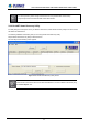
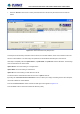
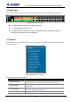
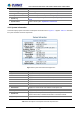
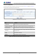
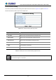
Table Of Contents

User’s Manual of POE-1200G / POE-2400G / HPOE-1200G / HPOE-2400G
4.2 Web Panel
At the top of the Web management page, the active panel displays the link status of management port and PoE ports.
Figure 4-2-1: Web panel screen
Green light indicates network data is sending or receiving.
Orange light indicates the PoE is in use.
Red light indicates the PoE port does not have enough power to enable. (It will happen only if user
assigns lower power to PD in the Total Limit mode.)
4.3 System
The System function provides system information which also allows user to manage the PoE Injector Hub system as Figure
4-2-2 is shown below:
Figure 4-2-2: System Function Menu
The page includes the following information:
Object Description
System Information
Display the MAC address, Software Version, Hardware Version, IP Address,
Subnet Mask, Gateway and Description. Explained in section 4.3.1.
IP Configuration
Allow to change the IP subnet address of PoE Injector Hub. Explained in
section 4.3.2.
NTP Configuration
Allow to set system time by manual or synchronize system time from Internet
NTP server. Explained in section 4.3.3.
Password Setting
Allow to change the username and password of PoE Injector Hub. Explained in
26