
User Manual
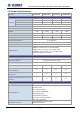
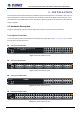
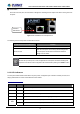
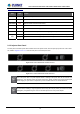
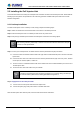
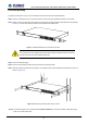
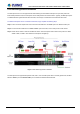
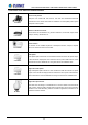
Table Of Contents

User’s Manual of POE-1200G / POE-2400G / HPOE-1200G / HPOE-2400G
POE-2400G / HPOE-2400G
LED Color Function
SYS Power Green Lights to indicate power on.
PoE1 Failure Red Lights to indicate 1st PoE module failure.
PoE2 Failure Red Lights to indicate 2nd PoE module failure.
Fan1 Failure Red Lights to indicate Fan1 has stopped.
Fan2 Failure Red Lights to indicate Fan2 has stopped.
PoE-in-use Green Lights to indicate that the port is in use and supplying 52V DC power.
Green
Lights to indicate the link through that port is successfully established at 1000Mbps.
Management
Port
Orange
Lights to indicate the link through that port is successfully established at 10/100Mbps.
2.1.3 Injector Rear Panel
The rear panel of the PoE Injector Hub indicates an AC inlet power socket, which accepts input power from 100 to 240V
AC, 50/60Hz. Figures 2-1-6 & 2-1-7 show the rear panel of the PoE Injector Hub.
Figure 2-1-6: POE-1200G/HPOE-1200G Rear Panel
Figure 2-1-7: POE-2400G/HPOE-2400G Rear Panel
The PoE Injector Hub is a power-required device, meaning PoE Injector Hub will not work till it is
powered. If your networks should be active all the time, please consider using UPS (Uninterrupted
Power Supply) for your device. It will prevent you from network data loss or network downtime.
In some areas, installing a surge suppression device may also help to protect your device from being
damaged by unregulated surge or current to the PoE Injector Hub or the power adapter.
16