User’s Manual of POE-1200G / POE-2400G / HPOE-1200G / HPOE-2400G
User’s Manual of POE-1200G / POE-2400G / HPOE-1200G / HPOE-2400G Trademarks Copyright © PLANET Technology Corp. 2015. Contents are subject to revision without prior notice. PLANET is a registered trademark of PLANET Technology Corp. All other trademarks belong to their respective owners.
User’s Manual of POE-1200G / POE-2400G / HPOE-1200G / HPOE-2400G TABLE OF CONTENTS 1. INTRODUCTION .............................................................................................................5 1.1 PACKAGE CONTENTS .................................................................................................................................. 5 1.2 PRODUCT DESCRIPTION ...........................................................................................................................
User’s Manual of POE-1200G / POE-2400G / HPOE-1200G / HPOE-2400G 4.3.8 System Log ...................................................................................................................................... 37 4.3.9 System Reboot................................................................................................................................. 38 4.3.10 Logout .............................................................................................................................
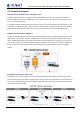
User’s Manual of POE-1200G / POE-2400G / HPOE-1200G / HPOE-2400G 1. INTRODUCTION Thanks you for purchasing PLANET Multi-port IEEE 802.3at PoE+ Managed Injector Hub. The description of this model is shown below: POE-1200G 12-Port 802.3at PoE+ Managed Gigabit Injector Hub (220W) HPOE-1200G 12-Port 802.3at PoE+ Managed Gigabit Injector Hub (360W) POE-2400G 24-Port 802.3at PoE+ Managed Gigabit Injector Hub (440W) HPOE-2400G 12-Port 802.3at PoE+ Managed Gigabit Injector Hub (720W) 1.
User’s Manual of POE-1200G / POE-2400G / HPOE-1200G / HPOE-2400G 1.2 Product Description High Power PoE for Public Service PoE Applications PLANET Managed PoE Injector Hub features multi-port Gigabit IEEE 802.3at PoE+ Web management, both IEEE 802.3af and IEEE 802.3at Power over Ethernet Plus (PoE+) that combine up to 30-watt power output and data per port over one Cat 5E/6 Ethernet cable.
User’s Manual of POE-1200G / POE-2400G / HPOE-1200G / HPOE-2400G PoE Schedule for Energy Saving Under the trend of energy saving worldwide and contributing to environment protection on the Earth, the PoE Injector Hub can effectively control the power supply besides its capability of giving high watts power.
User’s Manual of POE-1200G / POE-2400G / HPOE-1200G / HPOE-2400G Friendly Web Management Interface To efficiently manage the powered devices, the PoE Injector Hub provides simple Web management interface in which administrators can control the functions including port enable/disable, port priority, system configuration, change in user name and password, and smart features for powered devices.
User’s Manual of POE-1200G / POE-2400G / HPOE-1200G / HPOE-2400G 1.3 How to Use This Manual This User Manual is structured as follows: Section 2, Installation It explains the functions of PoE Injector Hub and how to physically install the PoE Injector Hub. Section 3, Management It contains information about the software function of the PoE Injector Hub. Section 4, Web Configuration The section explains how to manage the PoE Injector Hub through Web interface.
User’s Manual of POE-1200G / POE-2400G / HPOE-1200G / HPOE-2400G 1.
User’s Manual of POE-1200G / POE-2400G / HPOE-1200G / HPOE-2400G Hardware 19-inch rack mountable; 1U height Reset button for reset to default setting and system reboot LED indicators for PoE ready and PoE activity LED indicators for power alert and fan alert FCC Part 15 Class A, CE 11
User’s Manual of POE-1200G / POE-2400G / HPOE-1200G / HPOE-2400G 1.5 Product Specifications Product POE-1200G HPOE-1200G POE-2400G HPOE-2400G 3 3 3 3 12 x RJ45 12 x RJ45 24 x RJ45 24 x RJ45 “Data+Power” Output Ports 12 x RJ45 12 x RJ45 24 x RJ45 24 x RJ45 Management Port 1 x RJ45; 10/100/1000BASE-T, auto-negotiation, auto-MDI / MDIX Hardware Hardware Version “Data” Input Ports Interface 10/100/1000Mbps Data Rate 440 x 300 x 44 mm (1U height) Dimensions (W x D x H) Weight 3.9kg 4.
User’s Manual of POE-1200G / POE-2400G / HPOE-1200G / HPOE-2400G SNMP Trap for alarm notification of events Standards Conformance IEEE 802.3 10BASE-T Ethernet IEEE 802.3u 100BASE-TX Fast Ethernet IEEE 802.3ab 1000BASE-T Gigabit Ethernet IEEE 802.3at High Power over Ethernet IEEE 802.
User’s Manual of POE-1200G / POE-2400G / HPOE-1200G / HPOE-2400G 2. INSTALLATION This section describes the hardware features and installation of these PoE Injector Hubs on the desktop or rack mount. For easier management and control of the PoE Injector Hub, familiarize yourself with its display indicators, and ports. Front panel illustrations in this chapter display the unit LED indicators. Before deploying the PoE Injector Hub, please read this chapter completely. 2.
User’s Manual of POE-1200G / POE-2400G / HPOE-1200G / HPOE-2400G ■ Reset button At the left of the front panel, the reset button is designed for rebooting the PoE Injector Hub without turning off and on the power. Hardware Reset Button Figure 2-1-5: Reset Button of PoE Injector Hub The following is the summary table of reset button functions: Reset Button Pressed and Released About 1 second Function Reboot the PoE Injector Hub. Reset the PoE Injector Hub to Factory Default configuration.
User’s Manual of POE-1200G / POE-2400G / HPOE-1200G / HPOE-2400G POE-2400G / HPOE-2400G LED Color Function SYS Power Green Lights to indicate power on. PoE1 Failure Red Lights to indicate 1st PoE module failure. PoE2 Failure Red Lights to indicate 2nd PoE module failure. Fan1 Failure Red Lights to indicate Fan1 has stopped. Fan2 Failure Red Lights to indicate Fan2 has stopped. PoE-in-use Green Lights to indicate that the port is in use and supplying 52V DC power.
User’s Manual of POE-1200G / POE-2400G / HPOE-1200G / HPOE-2400G 2.2 Installing the PoE Injector Hub This section describes how to install your PoE Injector Hub and make connections to the PoE Injector Hub. Please read the following topics and perform the procedures in the order being presented. PLANET PoE Injector Hub does not need software configuration. 2.2.
User’s Manual of POE-1200G / POE-2400G / HPOE-1200G / HPOE-2400G 2.2.2 Rack Mounting To install the PoE Injector Hub in a 19-inch standard rack, follow the instructions described below. Step 1: Place your PoE Injector Hub on a hard flat surface, with the front panel positioned towards your front side. Step 2: Attach a rack-mount bracket to each side of the PoE Injector Hub with supplied screws attached to the package. Figure 2-2-1 shows how to attach brackets to one side of the PoE Injector Hub.
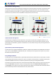
User’s Manual of POE-1200G / POE-2400G / HPOE-1200G / HPOE-2400G 2.2.3 Network Application Installation The PoE Injector Hub is not an equipment with data switching function between data ports. To inject PoE power and transmit data packets to PDs, the PoE Injector Hub is usually linked to an Ethernet switch. Typically, the Mid-span Injector is installed between regular Ethernet switch and PDs, and mostly it is located close to the Ethernet switch side.
User’s Manual of POE-1200G / POE-2400G / HPOE-1200G / HPOE-2400G 2.2.4 Power over Ethernet Powered Device Voice over IP phones Enterprise can install POE VoIP Phone, ATA and other Ethernet/non-Ethernet end-devices to the central where UPS is installed for un-interruptible power system 3~5 Watts and power control system. Wireless LAN Access Points Access Points can be installed in any location of Museum, Tourist Site, Airport, Hotel, 6~12 Watts Campus, Factory, Warehouse, etc.
User’s Manual of POE-1200G / POE-2400G / HPOE-1200G / HPOE-2400G 3 MANAGEMENT This chapter describes how to manage the PoE Injector Hub with the following topics included: - Overview - Management Method - Logging on to the PoE injector Hub 3.1 Overview The PoE injector hub provides a user-friendly, Web interface where you can perform various device configuration and management activities, including: System Power over Ethernet Tools 3.
User’s Manual of POE-1200G / POE-2400G / HPOE-1200G / HPOE-2400G 3.3 Management Method User can manage the PoE injector Hub by Web Management via a network connection. 3.3.1 Web Management The PoE Injector Hub can be configured through an Ethernet connection. The factory default IP address is 192.168.0.100 with subnet mask 255.255.255.0, so please make sure the manager PC must be set on the same IP subnet address.
User’s Manual of POE-1200G / POE-2400G / HPOE-1200G / HPOE-2400G 1. For security reason, please change and memorize the new password after this first setup. 2. Only accept command in lowercase letter under Web interface. 3.3.2 PLANET Smart Discovery Utility For easily listing the PoE Injector Hub in your Ethernet environment, Planet Smart Discovery Utility from user’s manual CD-ROM is an ideal solution. The following installation instructions guide you to running Planet Smart Discovery Utility.
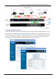
User’s Manual of POE-1200G / POE-2400G / HPOE-1200G / HPOE-2400G 1. Press the “Refresh” button for the currently-connected devices in the discovery list and the screen is shown as follows: Figure 3-1-4: Planet Smart Discovery Utility Screen This utility shows all necessary information from the devices, such as MAC address, device name, firmware version and device IP subnet address. It can also assign new password, IP subnet address and description of the devices.
User’s Manual of POE-1200G / POE-2400G / HPOE-1200G / HPOE-2400G 4 WEB CONFIGURATION The PoE Injector Hub provides Web interface for PoE smart function configuration and makes the PoE Injector Hub operate more effectively. They can be configured through the Web browser. A network administrator can manage and monitor the PoE Injector Hub from the local LAN. This section indicates how to configure the PoE Injector Hub to enable its smart function.
User’s Manual of POE-1200G / POE-2400G / HPOE-1200G / HPOE-2400G 4.2 Web Panel At the top of the Web management page, the active panel displays the link status of management port and PoE ports. Figure 4-2-1: Web panel screen Green light indicates network data is sending or receiving. Orange light indicates the PoE is in use. Red light indicates the PoE port does not have enough power to enable. (It will happen only if user assigns lower power to PD in the Total Limit mode.) 4.
User’s Manual of POE-1200G / POE-2400G / HPOE-1200G / HPOE-2400G section 4.3.4. Firmware Upgrade Allow to upgrade the latest firmware in the future. Explained in section 4.3.5. Configuration Setting Allow to back up or restore system configuration. Explained in section 4.3.6. Factory Default Allow to reset system to factory default setting. Explained in section 4.3.7. Allow to enable system log and to record system log. Explained in section 4.3.8.
User’s Manual of POE-1200G / POE-2400G / HPOE-1200G / HPOE-2400G 4.3.2 IP Configuration This section provides the IP Configuration of PoE Injector Hub as the screen in Figure 4-3-2 appears. Table 4-3-2 describes the IP Configuration object of PoE Injector Hub. Figure 4-3-2: IP Configuration Web Page Screen Object Description DHCP Client Allows to disable or enable the DHCP Client function of PoE Injector Hub. IP Address Allows to input new IP Address of PoE Injector Hub.
User’s Manual of POE-1200G / POE-2400G / HPOE-1200G / HPOE-2400G 4.3.3 NTP Configuration This section provides the NTP Configuration of PoE Injector Hub, the screen in Figure 4-3-3 appears and Table 4-3-3 describes the NTP Configuration object of PoE Injector Hub. Figure4-3-3: NTP Configuration Web page screen Object Description Current Time Allow input current time information of PoE Injector Hub. Enable NTP client update Allow disable or enable time update from NTP server of PoE Injector Hub.
User’s Manual of POE-1200G / POE-2400G / HPOE-1200G / HPOE-2400G 4.3.4 Password Setting This section provides the Password Setting of PoE Injector Hub as the screen in Figure 4-3-4 appears. Table 4-3-4 describes the Password Setting objects of PoE Injector Hub. Figure 4-3-4: Password Setting Web Page Screen Object Description User Name Allows to input current User Name of PoE Injector Hub. Old Password Allows to input current Password of PoE Injector Hub.
User’s Manual of POE-1200G / POE-2400G / HPOE-1200G / HPOE-2400G 4.3.5 Firmware Upgrade This section provides the firmware upgrade of PoE Injector Hub as the screen in Figure 4-3-5 appears. Figure 4-3-5: Firmware Upgrade Web Page Screen Please press “Browse” to locate the latest firmware of PoE Injector Hub that deposits in your PC. The screen in Figure 4-3-6 appears.
User’s Manual of POE-1200G / POE-2400G / HPOE-1200G / HPOE-2400G 4.3.6 Configuration Setting This function allows output the current PoE Injector Hub configuration as a file, and upload it to other PoE injector Hub for quick multi-devices setting. The description of the procedure and screens in the following appears. The screen in Figure 4-3-8 appears and Table 4-3-5 describes the Configuration Setting object of PoE Injector Hub.
User’s Manual of POE-1200G / POE-2400G / HPOE-1200G / HPOE-2400G Figure 4-3-10: File Save Screen ■ Configuration Upload Click the “Browse” button of the Configuration Setting Web page and the system would pop up the file selection screen to choose saved configuration. The screen in Figure 4-3-11 appears.
User’s Manual of POE-1200G / POE-2400G / HPOE-1200G / HPOE-2400G Select on the configuration file and then click “Upload”. After system has uploaded, the screen in Figure 4-3-12 appears. Figure 4-3-12: Configuration Upload Finished Screen When configuration has been uploaded, please re-login in the system again. Figure 4-3-13: System Login Screen 4.3.7 Factory Default This section describes resetting the PoE Injector Hub to factory default mode; the screen appears in Figure 4-3-14.
User’s Manual of POE-1200G / POE-2400G / HPOE-1200G / HPOE-2400G Please press the “Reset” button to take effect and the “Do you really want to reset the current settings to default?” pop window appears. Please press the “OK” button to continue the factory default process. The screen appears in Figure 4-3-15. Figure 4-3-15: Factory Default Web Page Screen Then the reboot screen appears in Figure 4-3-16 and press the “Reboot” button for rebooting the PoE Injector Hub.
User’s Manual of POE-1200G / POE-2400G / HPOE-1200G / HPOE-2400G The pop window with “Wait for 120 seconds while rebooting” appears; the screen in Figure 4-3-17 appears. Figure 4-3-17: Factory Default Web Page Screen After 120 seconds, press the “OK” button and then the main menu Web page screen appears in Figure 4-3-18.
User’s Manual of POE-1200G / POE-2400G / HPOE-1200G / HPOE-2400G 4.3.8 System Log This section provides the system log setting and information display of PoE Injector Hub; the screen in Figure 4-3-19 appears. Table 4-3-6 describes the system log setting object of PoE Injector Hub. Figure 4-3-19: System Log Web Page Screen Object Description Enable Log Provide disable or enable the system log function of PoE Injector Hub. Enable Remote Log Allow to send system log to remote log server.
User’s Manual of POE-1200G / POE-2400G / HPOE-1200G / HPOE-2400G 4.3.9 System Reboot This section provides the system reboot function of PoE Injector Hub; the screen in Figure 4-3-20 appears. Figure 4-3-20: System Reboot Web Page Screen Press the “Reboot” button to reboot the PoE Injector Hub; the screen in Figure 4-3-21 appears Figure 4-3-21: System Reboot Web Page Screen Wait for 120 seconds for completing the reboot process of PoE Injector Hub. 4.3.
User’s Manual of POE-1200G / POE-2400G / HPOE-1200G / HPOE-2400G Figure 4-3-23: Logout Web Page Screen Please input the password for entering into Web main menu screen of PoE Injector Hub; the screen in Figure 4-3-24 appears.
User’s Manual of POE-1200G / POE-2400G / HPOE-1200G / HPOE-2400G 4.4 SNMP The Simple Network Management Protocol (SNMP) is an application layer protocol that facilitates the exchange of management information between network devices. It is part of the Transmission Control Protocol/Internet Protocol (TCP/IP) protocol suit. SNMP enables network administrations to manage network performance, find and solve network problems, and plan for network growth.
User’s Manual of POE-1200G / POE-2400G / HPOE-1200G / HPOE-2400G Object Description SNMP Agent Provides disable or enable the SNMP Agent function of PoE Injector Hub. SNMP Read Community SNMP Write Community System Name System Location Contact Description Allow to input characters for SNMP Read Community of PoE Injector Hub. The maximum length is 30 characters. Allows to input characters for SNMP Write Community of PoE Injector Hub. The maximum length is 30 characters.
User’s Manual of POE-1200G / POE-2400G / HPOE-1200G / HPOE-2400G 4.5 Power over Ethernet Power Management: In a Power over Ethernet system, operating power is applied from a power source (PSU-power supply unit) over the LAN infrastructure to powered devices (PDs), which are connected to ports. Under some conditions, the total output power required by PDs can exceed the maximum available power provided by the PSU.
User’s Manual of POE-1200G / POE-2400G / HPOE-1200G / HPOE-2400G 4.5.1 PoE Configuration This section provides PoE (Power over Ethernet) Configuration and PoE output status of PoE Injector Hub; screen in Figure 4-5-2 appears. Table 4-5-2 describes the PoE Configuration object of PoE Injector Hub. Figure 4-5-2: PoE Configuration Web Page Screen Object Description System PoE Admin Mode Allows user to disable / enable PoE function. Power Supply Displays PoE power supply status.
User’s Manual of POE-1200G / POE-2400G / HPOE-1200G / HPOE-2400G Power Allocation POE-1200G POE-2400G HPOE-1200G HPOE-2400G OTP1 52 PoE Budget 210 watts 53 PoE Budget 410 watts 60 PoE Budget 345 watts 53 PoE Budget 690 watts OTP2 57 PoE Budget 200 watts 60 PoE Budget 380 watts 65 PoE Budget 330 watts 60 PoE Budget 660 watts Displays the current total power consumption status. This function provides input per port description and the available letters is 30.
User’s Manual of POE-1200G / POE-2400G / HPOE-1200G / HPOE-2400G PD Classifications A PD may be classified by the PSE based on the classification information provided by the PD. The intent of PD classification is to provide information about the maximum power required by the PD during operation. Class 0 is the default for PDs. However, to improve power management at the PSE, the PD may opt to provide a signature for Class 1 to 4. The PD is classified based on power.
User’s Manual of POE-1200G / POE-2400G / HPOE-1200G / HPOE-2400G The PoE Schedule Profile Web Screens are shown in Figure 4-5-3 and Table 4-5-4. Figure 4-5-3: PoE Configuration Web Page Screen The page includes the following information: Object Description Power Profile This PoE hub offers totally 24 profiles for user to configure PoE schedule. Function Allows user to enable or disable the profile. Include Port Provides user to select which PoE port he wants to apply to the profile.
User’s Manual of POE-1200G / POE-2400G / HPOE-1200G / HPOE-2400G 4.5.3 PoE Schedule PoE Schedule user can configure a duration time for PoE port as default value does not provide power; screen in Figure 4-5-4 and Table 4-5-5 show. Figure 4-5-4: PoE Schedule Web Page Screen The page includes the following information: Object Description Hour Allows user to configure PoE port open or close from hour 0 to 23. Allows user to configure PoE port open or close for a week. Sun.: Sunday. Mon.: Monday. Tue.
User’s Manual of POE-1200G / POE-2400G / HPOE-1200G / HPOE-2400G 4.5.4 PoE Schedule Profile Configuration Example Please enable NTP and correct PoE hub system time first and make sure System PoE Admin Mode is enabled; otherwise, you cannot configure PoE Schedule profile. You may see an error message as a screen shot is shown below. Screen in Figure 4-5-5 shows.
User’s Manual of POE-1200G / POE-2400G / HPOE-1200G / HPOE-2400G Press the Next >> button to set profile1 of PoE schedule, screen in Figure 4-5-7 appears. Figure 4-5-7: PoE Schedule Profile Configuration Please use mouse to click on the block about what time you want to supply power for PoE port. Then press the Apply button to save configuration. Please press the << Profile button back to the PoE schedule profile configuration page to go on to the next profile setting; screen in Figure 4-5-8 shows.
User’s Manual of POE-1200G / POE-2400G / HPOE-1200G / HPOE-2400G Figure 4-5-9: PoE Schedule Profile Configuration Please use mouse to click on the block about what time you want to supply power for PoE port and then press the Apply button to save configuration. Please press the << Profile button back to the PoE schedule profile configuration page to go on to the next profile setting; screen in Figure 4-5-10 shows.
User’s Manual of POE-1200G / POE-2400G / HPOE-1200G / HPOE-2400G Figure 4-5-12: PoE Schedule of PoE Camera Configuration User can press the Show button to display the current PoE schedule setting.
User’s Manual of POE-1200G / POE-2400G / HPOE-1200G / HPOE-2400G 4.5.5 PoE Alive Check Configuration The HPOE-1200G/2400G and POE-1200G/2400G PoE Switch can be configured to monitor connected PD’s status in real-time via ping action. Once the PD stops working and without response, the HPOE-1200G/2400G and POE-1200G/2400G PoE switches are going to restart PoE port power, and bring the PD back to work. It will greatly enhance the reliability and reduces administrator management burden.
User’s Manual of POE-1200G / POE-2400G / HPOE-1200G / HPOE-2400G Alarm: It means system will issue an alarm message via Syslog, SMTP. Reboot Time (30~180s) This column allows user to set the PoE device rebooting time. As there are so many kinds of PoE devices on the market, they have different rebooting times. The PD Alive-check is not a defining standard, so the PoE device on the market doesn’t report reboots done information to the HPOE-1200G/HPOE-2400G PoE switch.
User’s Manual of POE-1200G / POE-2400G / HPOE-1200G / HPOE-2400G 4.5.6 PoE Status This page allows user to see the usage of individual PoE Port. The screen in Figure 4-15-15 appears Figure 4-15-15: PoE Status Screenshot Buttons : Check this box to refresh the page automatically. Automatic refresh occurs every 3 seconds. : Refreshes the Web page and the current configuration if user doesn’t save it.
User’s Manual of POE-1200G / POE-2400G / HPOE-1200G / HPOE-2400G 5. POWER OVER ETHERNET OVERVIEW What is PoE? Based on the global standard IEEE 802.3af, PoE is a technology for wired Ethernet, the most widely installed local area network technology adopted today. PoE allows the electrical power necessary for the operation of each end-device to be carried by data cables rather than by separate power cords.
User’s Manual of POE-1200G / POE-2400G / HPOE-1200G / HPOE-2400G The data pairs are used. Since Ethernet pairs are transformer coupled at each end, it is possible to apply DC power to the center tap of the isolation transformer without upsetting the data transfer. In this mode of operation the pair on pins 3 and 6 and the pair on pins 1 and 2 can be of either polarity.
User’s Manual of POE-1200G / POE-2400G / HPOE-1200G / HPOE-2400G 6. THE POE PROVISION PROCESS While adding PoE support to networked devices is relatively painless, it should be realized that power cannot simply be transferred over existing Cat5e cables. Without proper preparation, doing so may result in damage to devices that are not designed to support provision of power over their network interfaces. The PSE is the manager of the PoE process.
User’s Manual of POE-1200G / POE-2400G / HPOE-1200G / HPOE-2400G 6.3 Start-up Once line detection and optional classification stages are completed, the PSE must switch from low voltage to its full voltage capacity (44-57 Volts) over a minimal amount of time (above 15 microseconds). A gradual startup is required, as a sudden rise in voltage (reaching high frequencies) would introduce noise on the data lines.
User’s Manual of POE-1200G / POE-2400G / HPOE-1200G / HPOE-2400G AC Disconnect This method is based on the fact that when a valid PD is connected to a port, the AC impedance measured on its terminals is significantly lower than in the case of an open port (disconnected PD). AC Disconnect detection involves the induction of low AC signal in addition to the 52 VDC operating voltage. The returned AC signal amplitude is monitored by the PSE at the port terminals.
User’s Manual of POE-1200G / POE-2400G / HPOE-1200G / HPOE-2400G APPENDIX A A.1 MDI Settings The Medium-Dependent Interface (MDI or RJ45) serves as the data/power interface between Ethernet elements. As such, it has two optional connection methods to carry the power. Named Alternative A & B, Table 1 details the two power feeding alternatives.
User’s Manual of POE-1200G / POE-2400G / HPOE-1200G / HPOE-2400G A.3 DATA OUT PoE Injector RJ45 Port Pin Assignments PIN NO RJ45 SIGNAL ASSIGNMENT 1 Output Transmit Data + 2 Output Transmit Data - 3 Receive Data + 4 Power - 5 Power - 6 Receive Data - 7 Power + 8 Power + A.4 RJ45 pin assignment of non-802.3af / 802.3at standard PD with PD with Mid-span PoE Mid-span RJ45 assignment Pin out of Cisco non-802.