User’s Manual POE-1200 POE-2400 IEEE 802.
Trademarks Copyright © PLANET Technology Corp. 2008. Contents subject to which revision without prior notice. PLANET is a registered trademark of PLANET Technology Corp. All other trademarks belong to their respective owners.
TABLE OF CONTENTS 1. INTRODUCTION ........................................................................................................................................... 1 1.1 PACKAGE CONTENTS .................................................................................................................................. 1 1.2 PRODUCT DESCRIPTION .............................................................................................................................. 1 1.3 HOW TO USE THIS MANUAL ..
1. INTRODUCTION 1.1 Package Contents Check the contents of your package for following parts: ● IEEE 802.
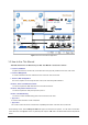
Figure 1-1 Power over Ethernet Application 1.3 How to Use This Manual This Web Smart Power over Ethernet Injector Hub User Manual is structured as follows: Section 2, Installation It explains the functions of POE-1200 / POE-2400 and how to physically install the POE-1200 / POE-2400. Section 3, Management It contains information about the software function of the POE-1200 / POE-2400. Section 4, Web Configuration The section explains how to manage the POE-1200 / POE-2400 through Web interface.
1.4 Product Features Interface 24 / 48-Port RJ-45 STP ¾ 12 / 24-Port “Data input” ¾ 12 / 24-Port “Data + Power output” 1 10/100Base-TX Management port PoE Complies with IEEE 802.3af Power over Ethernet Mid-Span PSE Up to 12/24 IEEE 802.3af devices powered Support PoE Power up to 15.
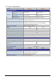
1.5 Product Specifications Product POE-1200 POE-2400 Hardware Specification “Data” Input Ports Interface “Data+Power” Output Ports Management Port LED 12 x RJ-45 STP 24 x RJ-45 STP 12 x RJ-45 STP 24 x RJ-45 STP 1 x RJ-45; 10/100Base-TX, auto-negotiation, auto-MDI System: Power x 1 Per PoE Port: PoE in Use x 1 Network Cable • 10Base-T: 2-Pair UTP Cat. 3, 4, 5, up to 100 m (328ft) • 100Base-TX: 2-Pair UTP Cat.
2. INSTALLATION This section describes the hardware features and installation of these PoE Injector Hub on the desktop or rack mount. For easier management and control of the PoE Injector Hub familiarize yourself with its display indicators, and ports. Front panel illustrations in this chapter display the unit LED indicators. Before deploy the PoE Injector Hub please read this chapter completely. 2.
The following is the summary table of Reset button functions: Reset Button Pressed and Released Function About 1 second Reboot the PoE Injector Hub Reset the PoE Injector Hub to Factory Default configuration. The PoE Injector Hub will reboot and load the default IP settings as below: Until the SYS LED lit off 。 Default Password: admin 。 Default IP address: 192.168.0.100 。 Subnet mask: 255.255.255.0 。 Default Gateway: 192.168.0.254 To press the RESET button about 10 seconds and then release.
Figure 2-4 POE-2400 Rear Panel Power Notice: 1. The device is a power-required device, it means, it will not work till it is powered. If your networks should active all the time, please consider using UPS (Uninterrupted Power Supply) for your device. It will prevent you from network data loss or network downtime. 2. In some area, installing a surge suppression device may also help to protect your device from being damaged by unregulated surge or current to the PoE Injector Hub or the power adapter. 2.
Step5: Supply power to the PoE Injector Hub. A. Connect one end of the power cable to the PoE Injector Hub. B. Connect the power plug of the power cable to a standard wall outlet. When the PoE Injector Hub receives power, the Power LED should remain solid Green. 2.2.2 Rack Mounting To install the PoE Injector Hub in a 19-inch standard rack, follow the instructions described below. Step1: Place your PoE Injector Hub on a hard flat surface, with the front panel positioned towards your front side.
Figure 2-6 Mounting thePoE Injector Hub in a Rack Step6: Proceeds with the steps 4 and steps 5 of session 2.2.1 Desktop Installation to connect the network cabling and supply power to your PoE Injector Hub. 2.2.3 Network Application Installation The PoE Injector Hub is not equipment with data switching function between data ports. To inject PoE power and transmit data packets to PDs, the PoE Injector Hub is usually link to an Ethernet switch.
Figure 2-7 Network application installation The PoE Injector Hub supports Data passive mode, that is, even the PoE Injector Hub is manual power off, the data between “DATA” port and “DATA+PoE” port can still be transmitted without data loss. The POE-1200 / POE-2400 Mid-Span Injector Hub doesn’t support Gigabit data rate. The Ethernet switches or PoE PDs with Gigabit interface will operate at 100Mpbs Full Duplex mode when connect to the Mid-Span Injector Hub. 2.2.
3 MANAGEMENT This chapter describes how to manage the Web Smart PoE Injector Hub. Topics include: - Overview - Management method - Logging on to the Web Smart PoE injector Hub 3.1 Overview The Web Smart PoE injector Hub provides a user-friendly, Web interface. Using this interface, you can perform various device configuration and management activities, including: System Power over Ethernet Tools 3.2 Requirements ■ Network cables. Use standard network (UTP) cables with RJ45 connectors.
Figure 3-1 Web Management over Ethernet 2. When the following login screen appears, please enter the default username "admin" and password “admin” (or the password you have changed via console) to login the main screen of PoE Injector Hub. The login screen in Figure 3-12 appears. Default IP Address: 192.168.0.100 Default Account: admin Default Password: admin Figure 3-2 Login screen 1. For security reason, please change and memorize the new password after this first setup. 2.
3.3.2 PLANET Smart Discovery Utility For easily list the PoE Injector Hub in your Ethernet environment, the Planet Smart Discovery Utility from user’s manual CD-ROM is an ideal solution. The following install instructions guiding you for run the Planet Smart Discovery Utility. 1. Deposit the Planet Smart Discovery Utility in administrator PC. 2. Run this utility and the following screen appears.
4. This utility show all necessary information from the devices, such as MAC Address, Device Name, firmware version, Device IP Subnet address, also can assign new password, IP Subnet address and description for the devices. 5. After setup completed, press “Update Device”, “Update Multi” or “Update All” button to take affect. The meaning of the 3 buttons above are shown as below: Update Device: use current setting on one single device. Update Multi: use current setting on choose multi-devices.
4 WEB CONFIGURATION The PoE Injector Hub provide Web interface for PoE smart function configuration and make the PoE Injector Hub operate more effectively - They can be configured through the Web Browser. A network administrator can manage and monitor the PoE Injector Hub from the local LAN. This section indicates how to configure the PoE Injector Hub to enable its smart function. 4.1 Manin Menu After a successful login, the main screen appears.
4.2 Web Panel At the top of the Web management page, the active panel displays the link status of management port and PoE ports. Figure 4-2 Main menu screen Green lit is the network data send or receiver, Orange lit is the PoE in use. 4.3 System The System function allows viewing system information, IP Configuration and Password Setting. As showed in Figure 4-3.
4.3.1 System Information The System information allows viewing system MAC Address, Software Version, Hardware Version, IP Address, Subnet Mask and Gateway.. As showed in Figure 4.4 Figure 4-4 System Information screen The page includes the following fields: Object Description MAC Address Specifies the PoE Injector Hub MAC address. Software Version The current software version running on the PoE Injector Hub . Hardware Version The current hardware version of the PoE Injector Hub.
The page includes the following configurable data: Object DHCP Client Description Choose what the PoE Injector Hub should do following power-up: transmit a DHCP request, or manual setting (Disable). The DHCP client function only works if you haven't assigned a static IP address that different than the PoE Injector Hub default IP. Once the default IP has been changed the DHCP will not effective and the PoE Injector Hub will continue using the manually entered static IP.
4.4 PoE Power Management: In a power over Ethernet system, operating power is applied from a power source (PSU-power supply unit) over the LAN infrastructure to powered devices (PDs), which are connected to ports. Under some conditions, the total output power required by PDs can exceed the maximum available power provided by the PSU. The system may a prior be planed with a PSU capable of supplying less power than the total potential power consumption of all the PoE ports in the system.
PoE Function Can enable or disable the PoE function. Priority Set port priority for the POE power management It can choose the “port priority”, value is “1~4”. High priority is “1”. Device class Class 0 is the default for PDs. However, to improve power management at the PSE, the PD may opt to provide a signature for Class 1 to 3. The PD is classified based on power. The classification of the PD is the maximum power that the PD will draw across all input voltages and operational modes.
4.5 Tools This function displays the PoE Injector Hub tools; include “System Reboot”, “Configuration Setting”, “Alert trap Configuration” and “Firmware upgrade”. As showed in Figure 4-8. Figure 4-8 Tools screen Object Description System Reboot Allow to reboot the PoE Injector Hub . Explained in section 4.5.1. Configuration Setting Allow to configuration setting of PoE Injector Hub . Explained in section 4.5.2. Alert Trap configuration Allow to configuration the alert trap of PoE Injector Hub .
4.5.2 Configuration Setting This function allows backup and restore the current configuration of PoE Injector Hub, or reset the converter to factory default. The description of the three items as follow and screen in Figure 4-10 appears. ■ Backup - To backup/save the current configuration to the storage block on this converter. ■ Restore – To restore the previous backup configuration from the storage block. ■ Factory – To reset the Injector Hub back to the factory default mode.
■ Restore The PoE Injector Hub will restore to previous backup/saved configuration while the “Restore” button be pressed. And please note that once the Restore button be pressed, Web interface will disconnected for a while. Reload the Web browser to re-login the system. Figure 4-13 Configuration restore screen ■ Factory Reset The Factory Reset button can reset the PoE Injector Hub back to the factory default mode.
4.5.3 Alert Trap Configuration This function displays the PoE Injector Hub alert trap configuration; include “enable” or “disable” the trap mode and set the alert IP address. As showed in Figure 4-16. Figure 4.16 Alert Trap Configuration screen Object Description Trap mode Can choose enable/disable to get the trap Alert IP address Asign one IP address of host to get SNMP trap Trap event Can choose which event can send the SNMP trap.
4.5.4 Firmware Upgrade This section provides firmware upgrade of PoE Injector Hub, after choose this function and the following screen appears in Figure 4-17. Please press “Update” button to continue following firmware upgrade process. Figure 4-17 Firmware Upgrade screen Please wait for two seconds and the page will show to next firmware upgrade web page, the screen in Figure 4-18 appears.
Figure 4-19 Firmware Upgrade screen Do not power off the PoE Injector Hub until the update progress is complete. Do not quit the Firmware Upgrade page without press the “Upgrade” button - after the image is loaded. Or the system won’t apply the new firmware. Users have to repeat the firmware upgrade processes again. 4.6 Logout Press this function; the Web interface will go back to login screen. The screens in Figure 4-20 and Figure 4-21 appear.
Figure 4-21 Login screen 27
5. POWER OVER ETHERNET OVERVIEW What is PoE? Based on the global standard IEEE 802.3af, PoE is a technology for wired Ethernet, the most widely installed local area network technology adopted today. PoE allows the electrical power necessary for the operation of each end-device to be carried by data cables rather than by separate power cords. New network applications, such as IP Cameras, VoIP Phones, and Wireless Networking, can help enterprises improve productivity.
The data pairs are used. Since Ethernet pairs are transformer coupled at each end, it is possible to apply DC power to the center tap of the isolation transformer without upsetting the data transfer. In this mode of operation the pair on pins 3 and 6 and the pair on pins 1 and 2 can be of either polarity.
6. THE POE PROVISION PROCESS While adding PoE support to networked devices is relatively painless, it should be realized that power cannot simply be transferred over existing CAT-5 cables. Without proper preparation, doing so may result in damage to devices that are not designed to support provision of power over their network interfaces. The PSE is the manager of the PoE process.
6.3 Start-up Once line detection and optional classification stages are completed, the PSE must switch from low voltage to its full voltage capacity (44-57 Volts) over a minimal amount of time (above 15 microseconds). A gradual startup is required, as a sudden rise in voltage (reaching high frequencies) would introduce noise on the data lines. Once provision of power is initiated, it is common for inrush current to be experienced at the PSE port, due to the PD’s input capacitance.
7 TROUBLESHOOTING This chapter contains information to help you solve problems. If the Device is not functioning properly, make sure the Ethernet Injector Hub was set up according to instructions in this manual. What is the power output of each IEEE 802.af PoE port? Solution: Each PoE port supports 48VDC, 350mA, max 15.4 watts power output. Detect and inject by the standard of IEEE 802.3af. How to let my non IEEE 802.
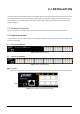
APPENDIX A A.1 MDI Settings The Medium-Dependant Interface (MDI or RJ-45) serves as the data/power interface between Ethernet elements. As such, it has two optional connection methods, to carry the power. named Alternative A & B. Table 1 details the two power feeding alternatives.
A.3 DATA OUT PoE Injector RJ-45 Port Pin Assignments PIN NO RJ-45 SIGNAL ASSIGNMENT 1 Output Transmit Data + 2 Output Transmit Data - 3 Receive Data + 4 Power + 5 Power + 6 Receive Data - 7 Power - 8 Power - A.4 RJ-45 pin assignment of non-802.3af standard PD with PD with Mid-Spain POE Mid-Span RJ-45 assignment Pin out of Cisco non-802.
Before you powered PD, please check the RJ-45 connector pin assignment follow IEEE 802.3af standard, otherwise you may need change one of the RJ-45 connector pin assignment, which attacted with the UTP cable.
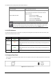
APPENDIX B B.1 Power over Ethernet Compatibility test No. PDs PoE Output Note 1 [PLANET POE-151S-12V] + [PLANET ICA-500] 9.6W 2 [PLANET POE-151S-12V] + PLANET ICA310 6.4W 3 [PLANET POE-152S-12V] + [PLANET ICA-500] 7.3W 4 [PLANET POE-151S-5V] + [Sparklan A+G AP] 5.7W~7.6W 5 [PLANET POE-151S-12] + IR338 5.1W LED Off 6 [PLANET POE-151S-12] + IR338 13.5W~14.3W LED On 7 PLANET VIP-155PT 3W 8 PLANET VIP-154PT 4.9W~5.6W 9 PLANET VIP-550PT 4~4.5W 10 PLANET WAP-4060PE 4.
EC Declaration of Conformity For the following equipment: *Type of Product: 12-Port IEEE 802.3af Injector Hub *Model Number: POE-1200 * Produced by: Manufacturer‘s Name : Manufacturer‘s Address: PLANET Technology Corp. 11F, No 96, Min Chuan Road Hsin Tien, Taipei, Taiwan , R.O.C. is herewith confirmed to comply with the requirements set out in the Council Directive on the Approximation of the Laws of the Member States relating to Electromagnetic Compatibility Directive on (89/336/EEC).
EC Declaration of Conformity For the following equipment: *Type of Product: 24-Port IEEE 802.3af Injector Hub *Model Number:POE-2400 * Produced by: Manufacturer‘s Name : Manufacturer‘s Address: PLANET Technology Corp. 11F, No 96, Min Chuan Road Hsin Tien, Taipei, Taiwan , R.O.C. is herewith confirmed to comply with the requirements set out in the Council Directive on the Approximation of the Laws of the Member States relating to Electromagnetic Compatibility Directive on (89/336/EEC).