4-Port 10/100Mbps +1/2 100FX Fiber Port Industrial Fast Ethernet Switch ISW-511 / ISW-621Series User's Manual
Trademarks Copyright © PLANET Technology Corp. 2009. Contents subject to revision without prior notice. PLANET is a registered trademark of PLANET Technology Corp. All other trademarks belong to their respective owners. Disclaimer PLANET Technology does not warrant that the hardware will work properly in all environments and applications, and makes no warranty and representation, either implied or expressed, with respect to the quality, performance, merchantability, or fitness for a particular purpose.
communications. Operation of this equipment in a residential area is likely to cause harmful interference in which case the user will be required to correct the interference at his own expense. CE Mark Warning This is a Class A product. In a domestic environment, this product may cause radio interference, in which case the user may be required to take adequate measures.
TABLE OF CONTENTS 1. INTRODUCTION......................................................................... 6 1.1 Package Contents................................................................ 6 1.2 How to Use This Manual ..................................................... 6 1.3 Product Features.................................................................. 7 Physical Port........................................................................ 7 Layer 2 Features...............................
4. SWITCH OPERATION..................................................................24 4.1 Address Table.....................................................................24 4.2 Learning............................................................................24 4.3 Forwarding & Filtering.........................................................24 4.4 Store-and-Forward..............................................................24 4.5 Auto-negotiation....................................................
1. INTRODUCTION 1.1 Package Contents Check the contents of your package for following parts: ● Industrial Fast Ethernet Switch x 1 ● User's Manual x 1 ● DIN Rail Kit x 1 ● Wall Mount Kit x 1 If any of these are missing or damaged, please contact your dealer immediately, if possible, retain the carton including the original packing material, and use them against to repack the product in case there is a need to return it to us for repair. 1.
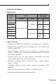
1.3 Product Features Physical Port Fiber Optical Interface Ports Model Name Copper Optical ISW-511 ISW-511T 1 x 100Base-FX ISW-511S15 ISW-511TS15 ISW-621 4 x 10/100Base-TX ISW-621T 2 x 100Base-FX ISW-621S15 ISW-621TS15 Mode Distance Multimode 2km Singlemode 15km Multimode 2km Singlemode 15km Layer 2 Features □ Complies with IEEE 802.3, IEEE 802.
□ CSMA/CD Protocol Industrial Case / Installation □ IP-30 Metal case / Protection □ DIN Rail and Wall Mount Design □ 12 to 48V DC, redundant power with polarity reverse protect function and connective removable terminal block for master and slave power □ -10 to 60 Degree C operation temperature on ISW-511 / ISW511S15 / ISW-621 / ISW-621S15 □ -40 to 75 Degree C operation temperature on ISW-511T / ISW511TS15 / ISW-621T / ISW-621TS15
1.4 Product Specifications Model ISW-511 ISW-511S15 Hardware Specification Copper Fiber Optical Ports 4 x 10/100Base-TX, Auto-negotiation, Auto-MDI/MDI-X Cable 10Base-T: 2-pair UTP Cat. 3, 4, 5 cable (100meters, max.) 100Base-TX: 2-pair UTP Cat. 5 cable (100meters, max.) Port 1 x 100Base-FX Cable 50/125μm or 62.
Model ISW-511T ISW-511TS15 Hardware Specification Copper Fiber Optical Ports 4 x 10/100Base-TX, Auto-negotiation, Auto-MDI/MDI-X Cable 10Base-T: 2-pair UTP Cat. 3, 4, 5 cable (100meters, max.) 100Base-TX: 2-pair UTP Cat. 5 cable (100meters, max.) Port 1 x 100Base-FX Cable 50/125μm or 62.
Model ISW-621 ISW-621S15 Hardware Specification Copper Fiber Optical Ports 4 x 10/100Base-TX, Auto-negotiation, Auto-MDI/MDI-X Cable 10Base-T: 2-pair UTP Cat. 3, 4, 5 cable (100meters, max.) 100Base-TX: 2-pair UTP Cat. 5 cable (100meters, max.) Port 2 x 100Base-FX Cable 50/125μm or 62.
Model ISW-621T ISW-621TS15 Hardware Specification Copper Fiber Optical Ports 4 x 10/100Base-TX, Auto-negotiation, Auto-MDI/MDI-X Cable 10Base-T : 2-pair UTP Cat. 3, 4, 5 cable (100meters, max.) 100Base-TX : 2-pair UTP Cat. 5 cable (100meters, max.) Port 2 x 100Base-FX Cable 50/125μm or 62.
2. INSTALLATION This section describes the functionalities of the Industrial Fast Ethernet Switch’s components and guides how to install it on the desktop. Basic knowledge of networking is assumed. Please read this chapter completely before continuing. In the following section, the term “Industrial Fast Ethernet Switch” means the ISW-511 / ISW-621 series. 2.
2.1.1 Switch Front Panel Figure 2-1 & 2-2 & 2-3 & 2-4 shows a front panel of Industrial Fast Ethernet Switch.
Figure 2-3 ISW-511T / ISW-511TS15 front panel Figure 2-4 ISW-621T / ISW-621TS15 front panel 15
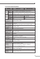
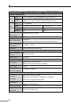
2.1.2 LED Indicators LED Color Function P1 Green Lit: indicate the power 1 has power. P2 Green Lit: indicate the power 2 has power. FAULT Green Lit: indicate the either power 1 or power 2 has no power. 100 Green Fiber Optical Green Lit: indicate the Switch is successfully connecting to the network at 100Mbps. Copper Off: indicate that the Switch is successfully connecting to the network at 10Mbps. Green Lit: indicate the link through that port is Fiber successfully established.
2.1.4 Wiring the Power Inputs The 6-contact terminal block connector on the top panel of Industrial Fast Ethernet Switch is used for two DC redundant powers input. Please follow the steps below to insert the power wire. 1. Insert positive / negative DC power wires into the contacts 1 and 2 for POWER 1, or 5 and 6 for POWER 2. V1- V1 + V2 - V2 + 2. Tighten the wire-clamp screws for preventing the wires from loosing.3.
2.1.5 Wiring the Fault Alarm Contact The fault alarm contacts are in the middle of the terminal block connector as the picture shows below. Inserting the wires, the Industrial Fast Ethernet Switch will detect the fault status of the power failure, or port link failure (available for managed model) and then forms an open circuit. The following illustration shows an application example for wiring the fault alarm contacts. 1 2 3 4 5 6 Insert the wires into the fault alarm contacts Note 18 1.
2.2 Mounting Installation This section describes how to install the Industrial Fast Ethernet Switch and make connections to it. Please read the following topics and perform the procedures in the order being presented. Note In the installation steps below, this Manual use IGS801 (PLANET 8 Port Industrial Gigabit Switch) as the example. However, the steps for PLANET Industrial Switch & Industrial Media Converter are similar. 2.2.
1 2 Step 2: Lightly press the button of DIN-Rail into the track. Step 3: Check the DIN-Rail is tightly on the track. Step 4: Please refer to following procedures to remove the Industrial Fast Ethernet Switch from the track. 1 2 Step 5: Lightly press the button of DIN-Rail for remove it from the track.
2.2.2 Wall Mount Plate Mounting To install the Industrial Fast Ethernet Switch on the wall, please follows the instructions described below. Step 1: Remove the DIN-Rail from the Industrial Fast Ethernet Switch; loose the screws to remove the DIN-Rail. Step 2: Place the wall mount plate on the rear panel of the Industrial Fast Ethernet Switch. Step 3: Use the screws to screw the wall mount plate on the Industrial Fast Ethernet Switch.
3. Application In this paragraph, we will describe how to install Industrial Fast Ethernet Switch and the installation points for the attention.
Installation Steps Step 1: Unpack the Industrial Fast Ethernet Switch. Step 2: Check the DIN-Rail is screwed on the Industrial Fast Ethernet Switch. (Please refer to DIN-Rail Mounting section for DINRail installation. If the DIN-Rail is not screwed on the Industrial Fast Ethernet Switch.). If you want to wall mount the Industrial Fast Ethernet Switch, then please refer to Wall Mount Plate Mounting section for wall mount plate installation.
4. Switch Operation 4.1 Address Table The Industrial Fast Ethernet Switch is implemented with an address table. This address table composed of many entries. Each entry is used to store the address information of some node in network, including MAC address, port no, etc. This information comes from the learning process of Industrial Fast Ethernet Switch. 4.2 Learning When one packet comes in from any port. The Industrial Fast Ethernet Switch will record the source address, port no.
Therefore, no error packets occurrence, it is the best choice when a network needs efficiency and stability. The Industrial Fast Ethernet Switch scans the destination address from the packet-header, searches the routing table provided for the incoming port and forwards the packet, only if required. The fast forwarding makes the switch attractive for connecting servers directly to the network, thereby increasing throughput and availability.
5. TROUBLESHOOTING This chapter contains information to help you solve issues. If the Industrial Fast Ethernet Switch is not functioning properly, make sure the Industrial Fast Ethernet Switch was set up according to instructions in this manual. The per port LED is not lit Solution: Check the cable connection of the Industrial Fast Ethernet Switch. Performance is bad Solution: Check the speed duplex mode of the partner device.
APPENDIX A: NETWORKING CONNECTION A.1 Switch’s RJ-45 Pin Assignments 10/100Mbps, 10/100Base-TX RJ-45 Connector pin assignment Contact MDI Media Dependant Interface MDI-X Media Dependant Interface -Cross 1 Tx + (transmit) Rx + (receive) 2 Tx - (transmit) Rx - (receive) 3 Rx + (receive) Tx + (transmit) 4, 5 6 7, 8 Not used Rx - (receive) Tx - (transmit) Not used A.
Straight Cable 1 2 3 4 5 6 7 8 SIDE 1 1 2 3 4 5 6 7 8 SIDE 2 SIDE 1 1 = White/Orange 2 = Orange 3 = White/Green 4 = Blue 5 = White/Blue 6 = Green 7 = White/Brown 8 = Brown SIDE 2 1 = White/Orange 2 = Orange 3 = White/Green 4 = Blue 5 = White/Blue 6 = Green 7 = White/Brown 8 = Brown SIDE 1 1 = White/Orange 2 = Orange 3 = White/Green 4 = Blue 5 = White/Blue 6 = Green 7 = White/Brown 8 = Brown SIDE 2 1 = White/Green 2 = Green 3 = White/Orange 4 = Blue 5 = White/Blue 6 = Orange 7 = White/Brown 8 = Brown