
User's Manual
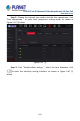
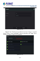

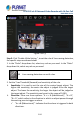
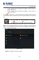

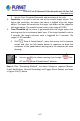
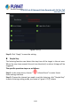
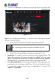
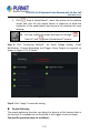
Table Of Contents
- Copyright
- Declaration
- Contents
- Chapter 1 Outlines and Features
- Chapter 2 NVR Appearance
- Chapter 3 Connecting NVR
- Chapter 4 NVR Startup
- Chapter 5 NVR Menu
- Chapter 6 Web Operation
- 6.1 Internet connection
- 6.2 Browser Login
- 6.3 Active X download, installation
- 6.4 Live View
- 6.5 Configuration
- 6.5.1 Local Config
- 6.5.2 Camera
- 6.5.3 Storage
- 6.5.3.1 Channel Recording
- Step 1: In the main interface, click "Configuration → Storage→ Channel Recording" to enter the recording setting interface, as shown in Figure 6-14 below.
- Figure 6-14
- Step 2: Set parameters, see the table below.
- Table 6-1
- Step 3: Click "Save" to complete configuration.
- Encode
- In the main interface, click "Configuration →Record →Encode" to enter the encoding setting interface, as shown in Figure 6-15 below. Here you can view and set the encoding parameter values for accessing the IPC. The relevant parameters and NVR-side se...
- Figure 6-15
- 6.5.3.2 Storage Manage
- HDD
- In the main interface, click "Configuration →Storage →Storage Manage" to enter the HDD interface, as shown in Figure 6-16 below. Here you can view the HDD information of the connected device and format the hard disk. The operation steps of formatting ...
- Figure 6-16
- Cloud Storage
- In the main interface, click "Configuration →System →Network →Cloud Storage" to enter Cloud Storage and IPEYE setting interface, as shown in Figure 6-17 below. Here you could enable and set the function of Cloud Storage and IPEYE, the specific setting...
- Figure 6-17
- 6.5.4 System
- 6.5.5 Maintain
- 6.6 Playback
- 6.7 Picture
- Chapter 7 Appendix

H.265 25-ch 4K Network Video Recorde with 16-Port PoE
NVR-2500 Series
165
"A->B" indicates that the object will trigger an alarm when it
crosses from A to B.
"B->A" indicates that the object will trigger an alarm when it
crosses from B to A.
3. Click"
Draw A Line", move the mouse to the preview screen and click
the left mouse button in sequence to draw the two endpoints of the warning
line.
You can
modify the drawn warning line through
the" Clear All" and " Draw A Line" button.
Step 4: Click "Processing Method", set alarm linkage as required (Buzzer
Alarm, E-mail Notification, Channel Recording and Trigger Alarm Output), as
shown in Figure 5-68 ○2 below.
Figure 5-68 ○2
Step 5: Click "Apply" to save the setting.