
User's Manual
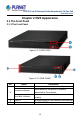
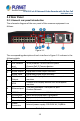
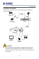
Table Of Contents
- Copyright
- Declaration
- Contents
- Chapter 1 Outlines and Features
- Chapter 2 NVR Appearance
- Chapter 3 Connecting NVR
- Chapter 4 NVR Startup
- Chapter 5 NVR Menu
- Chapter 6 Web Operation
- 6.1 Internet connection
- 6.2 Browser Login
- 6.3 Active X download, installation
- 6.4 Live View
- 6.5 Configuration
- 6.5.1 Local Config
- 6.5.2 Camera
- 6.5.3 Storage
- 6.5.3.1 Channel Recording
- Step 1: In the main interface, click "Configuration → Storage→ Channel Recording" to enter the recording setting interface, as shown in Figure 6-14 below.
- Figure 6-14
- Step 2: Set parameters, see the table below.
- Table 6-1
- Step 3: Click "Save" to complete configuration.
- Encode
- In the main interface, click "Configuration →Record →Encode" to enter the encoding setting interface, as shown in Figure 6-15 below. Here you can view and set the encoding parameter values for accessing the IPC. The relevant parameters and NVR-side se...
- Figure 6-15
- 6.5.3.2 Storage Manage
- HDD
- In the main interface, click "Configuration →Storage →Storage Manage" to enter the HDD interface, as shown in Figure 6-16 below. Here you can view the HDD information of the connected device and format the hard disk. The operation steps of formatting ...
- Figure 6-16
- Cloud Storage
- In the main interface, click "Configuration →System →Network →Cloud Storage" to enter Cloud Storage and IPEYE setting interface, as shown in Figure 6-17 below. Here you could enable and set the function of Cloud Storage and IPEYE, the specific setting...
- Figure 6-17
- 6.5.4 System
- 6.5.5 Maintain
- 6.6 Playback
- 6.7 Picture
- Chapter 7 Appendix

H.265 25-ch 4K Network Video Recorde with 16-Port PoE
NVR-2500 Series
16
2.2.2 Built-in PoE device rear panel introduction
The schematic diagram of the rear panel of the built-in PoE device is as
follows:
Figure 2-3
The corresponding description of each interface in Figure 2-3 is shown in the
following table:
No.
Name
Description
C Ethernet port
1 10/100/1000BASE-T MDI/MDI-X port
Connect Network
D
HD Video
Output
Connect HD display devices such as computer
monitors
VGA
Connect VGA display devices such as computer
monitors
E
USB port
Connect the mouse, U disk or removable hard disk
F
Audio Input
Equipment audio input interface
Audio output
Equipment audio output interface
G
Power
Connector
DC External 12V, 4A Power Adapter
Device power connector