Mobile IP Roaming Gateway MAP-2105 User’s Manual 1
Copyright Copyright (C) 2006 PLANET Technology Corp. All rights reserved. The products and programs described in this User’s Manual are licensed products of PLANET Technology, This User’s Manual contains proprietary information protected by copyright, and this User’s Manual and all accompanying hardware, software, and documentation are copyrighted.
Trademarks The PLANET logo is a trademark of PLANET Technology. This documentation may refer to numerous hardware and software products by their trade names. In most, if not all cases, these designations are claimed as trademarks or registered trademarks by their respective companies. Revision User’s Manual for PLANET Mobile IP Roaming Gateway: Model: MAP-2105 Rev: 1.0 (July 2006) Part No.
TABLE OF CONTENTS Chapter 1 Introduction .......................................................................................1 1.1 Features ......................................................................................................1 1.2 Package Contents .......................................................................................1 1.3 Network Planning ........................................................................................1 1.4 Hardware Installation...................
4.3.2 Status > System..................................................................................45 4.3.3 Status > MLRD ...................................................................................46 4.3.4 Config > System .................................................................................47 4.3.5 Config > Network > WAN....................................................................48 4.3.6 Config > Network > Route.................................................................
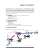
Chapter 1 Introduction The MAP-2105 is a mobile IP roaming gateway which is specifically designed for PLANET wireless mesh network. It offers the full “mobility” to all users. Not like the layer-2 only capability in ordinary AP, the “mobility” defined in MAP-2105 is the ability of a user to change its attached node from one mesh AP to another while maintaining all existing communications and using the same IP address at this new link.
The MAP-2105 should connect to the network that provide DHCP services (the first time installation) In this guide, we will base on XRT-401D (Internet Broadband Router) as the example for DHCP server, switch and router, this installation can vary on the network planning. The MAP-2105 should be installed in the same subnet to the Mesh Gateway for optimal performance.
https://192.168.0.100. 6. The pop-up screen will ask for user name and password. By default, please key in “admin” for both name and password. Then bring up the screen. 7. Now, the MAP-2105 is ready for services.
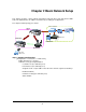
Chapter 2 Basic Network Setup This chapter describes a basic network environment formed by three mesh AP and one MAP2105. The administrators can add the mesh AP freely according to real application. The sample network topology is as below. Ethernet Switch Mesh G t Router MAP-2105 Mesh Relay DHCP Server Mesh Relay 802.
[Configuration -> Local Service -> Mobile IP] Enable Transparent Mobile IP Service: checked Mobile IP Community Name: PLANET (it must be identical for all nodes in the same mesh network) Mobile Location Register Address: 10.16.1.
Mobile IP Community Name: PLANET (it must be identical for all nodes in the same mesh network) Mobile Location Register Address: 10.16.1.7 (the IP address assigned in Gateway VPN Server screen) Step 4: Reboot the Relay Step 5: MAP-2105 Configuration: [Configuration -> Local Service -> VPN Client] Enable PPTP Client: checked VPN Server: 192.168.0.99 (the Gateway WAN IP address) Remote Subnet: 10.0.0.0 (the subnet of Gateway’s Backhaul radio IP) Remote Netmask: 255.0.0.
CN Info Two correspondent nodes connected with relevant info. Client Info Info of the mobile station recorded in the MAP-2105.
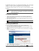
Chapter 3 Web Configuration To start the web configuration, 1. Start the web browser 2. Enter https://IP Address of the MAP-2105, in the address box (make sure HTTPS, but not HTTP) 3. Accept the security certificate and click ‘Yes’ to proceed. 4. The Web-based configuration login page opens after the security certification has been accepted. 5. Enter the user name and password. By default, the user name and password are both set to ‘admin’.
6. After login successfully, the Web-based configuration main page is open, which is appealed as below. The following table describes the navigation button in brief. Link Description System Settings Display the system settings page, which consists of general information about the system Network Display or hide the links to WAN and Route.
contains the configuration to updates password for web management server SNMP contains the configuration for Simple Network Management Protocol Syslog Server contains the configuration for syslog server Tools Display or hide the links to Ping, Download, Firmware Update, and Settings Ping ping tools for network diagnostic Download contains configuration for TFTP file transfer Firmware Update web management firmware management Settings contains the configuration for web management server settings Reboot Di
System Settings contains the following: Device Name Enter a name for the device. Device Location Enter a location that the device is located. Contact Name Enter a name for the person to be contacted when consultant is needed regarding to the device. Contact Email Enter an email address to be contacted when consultant is needed. Contact Phone Enter a phone number to be contacted when consultant is needed. Object ID Display the object identification (OID) of Simple Network Management Protocol.
Display the IP address of the WAN interface of this device. For the first time operation, it display IP obtained from DHCP server. “Apply” Button Submit the changes. New settings are active after the device reboot. 3.2 Network 3.2.1 WAN DHCPC Dynamically assigns an IP to this device. Static IP Specify an IP address to this device. Please complete the network parameters portion. Configure Details and Save This button will lead to page according to the selected Interface Type mentioned above.
-- Static IP selected Please enter the required field as follow: IP Enter an IP address for this device Netmask Enter a network mask for this IP Apply Press this button to save new settings. Back Back to previous page Gateway IP Address Specify the gateway IP address for this device. Leave blank when DHCPC is enabled, otherwise this entry will override the information obtained from DHCP server. Primary DNS Server IP Address Specify the IP address of the primary DNS server for this device.
Secondary DNS Server IP Address Specify the IP address of the Secondary DNS server for this device. Leave blank when DHCPC is enabled, otherwise this entry will override the information obtained from DHCP server. Domain Name Specify the domain name. Apply Press this button to save new settings for Gateway IP Address, Primary and Secondary DNS Server IP Address, and Domain Name. 3.2.
Static Routing Entry contains the following parameters: Subnet Enter a subnet IP address. Netmask Enter a netmask of the subnet IP address above. Gateway Select either gateway or device so that the traffic is through this selection. Please enter IP address for gateway selection. Device Select either WAN or VPN from the drop down list. All the traffic from the specified subnet will be routed to this selected device. Comment Optional comment can be added into this field.
3.3 Local Service 3.3.1 MLRD Mobile Location Register contains the following parameters: Enable Mobile Location Register Service Enable or disable mobile location register service. Mobile IP Community Name Enter a common name for this entry. Mobile node’s community name must be same for all participating mobile IP node. Enable Backup Mobile Location Register Enable or disable the backup mechanism to another server.
3.3.2 VPN Client VPN contains the following parameters: Status Display the status of the VPN client. Enable PPTP client Enable or disable PPTP client. VPN Server Enter the IP address of the VPN server.
Enter the username which is pre-defined in VPN server of MESH Gateway. Password Enter the password which is pre-defined in VPN server of MESH Gateway. Enable server-side authentication Enable or disable server-side authentication. Servers Username Enter the server username for server to authenticate. Servers Password Enter the server password for server to authenticate. “Save Config” button Press this button to save new settings. Back Link to previous page. 3.3.
Server 2 Enter IP address or hostname for the NTP server. Server 3 Enter IP address or hostname for the NTP server. Timezone Click on the drop-down button and select the desired country. “Apply” button Press this button to save new settings 3.4 System Management 3.4.1 Password Password contains the following parameters: New Password Enter a new password. New Password (repeat) Repeat the password entered above to confirm the changes. “Apply” button Press this button to save new settings. 3.4.
SNMP contains the following parameters: SNMP version Select from v1 v2, v3, or both. SNMPv2 Read only community Enter the v2 read only community.
Read/Write community Enter the v2 read write community. SNMPv3 Read only username Enter the v3 read only username. Read/Write username Enter the v3 read write username. Secret password Enter the password for the username configured above. Secret passphrase Enter the passphrase for the username configured above. Access Control From WAN interface Check or uncheck the checkbox to allow or ban access for SNMP configuration purposes from WAN interface.
Enable or disable SNMP trap for this device. Trap Community Enter the trap server community. Destination Enter the IP address of the trap server. Authentication failures Check or uncheck the checkbox to enable or disable sending of traps when authentication failures occur. “Apply” button Press this button to save new settings. 3.4.
Press this button to restore default configuration for this page. 3.5 Tools 3.5.1 Ping Ping contains the following parameters: Ping Enter an IP address to ping. Number of pings Enter the numbers of ping packets to be send before displaying the result. “Start” button Start the ping command. Output Display the result of the ping command.
3.5.2 Download Download contains the following parameters: Release Version Display the revision number of the firmware. TFTP Information Server IP Address Enter the TFTP server IP address. File Name Enter the filename of the file located at the TFTP server. File Type Please select either “config” or “firmware”. File Operation Please select either “upload”, “download”, “download and reboot”. Upload will send the file from device to TFTP server. Note that only config can be uploaded to the server.
“Apply” button Press this button to save new settings and begin TFTP operation. 3.5.3 Firmware Update Firmware page contains the following parameters: “Browse” button Press this button to browse for firmware. “Upload” button Press this button to upload the new firmware. Do not switch off the device, or do any other configuration settings. Wait for it to finish. Failure in firmware update may cause the device to be unusable.
3.5.
Settings contain the following parameters: Save Config Click on the “mlrd.cfg” hyperlink to save the current configuration into local computer. This configuration file can be used for debugging purpose as well as cloning settings to all other devices. Restore Config Select the proper configuration to be restored. Press the “Browse” button to select the correct file to be restored. After this, Press the “Upload” button to upload the selected file. This action will override current configuration.
Press this button to save new settings. “Use Default” button Press this button to restore the factory default configuration for this page. 3.6 Reboot Reboot contains the following parameters: Please enter the time to reboot (seconds) Enter a delay value so that the device will only reboot after the requested delay of time. “Reboot” button Press this button to reboot the device. If a delay is specified, it will wait for that amount of time before rebooting the device. 3.
3.8.1 System System contains the following parameters: Uptime Display the uptime of the device since last booting. Hardware Display the state of the hardware. CPU Display information about the Central Processing Unit.
Display information about the memory state of the device. Firmware Display the revision version of the firmware. 3.8.2 Interfaces Interfaces contain the following parameters WAN Information Link to more detail information about the WAN interface.
Interface Display the state of the interface. Running means the interface is up and running. Hardware Address Display the hardware address of the interface. IP address Display the IP address of the interface.
3.8.3 Services Services page will display the status of each process and a corresponding “Restart” button to restart that particular service. 3.8.
CN Info Display the information of connected Correspondent Node. Client Info Display the information of client register to the MAP-2105. 3.8.5 Route Route contains the following parameters: “Refresh” button Press this button to refresh the content of the output area. Output Display the output of route command.
3.8.6 Syslog Syslog contains the following parameters: “Refresh” button Press this button to refresh the content of Output area. Output Display the output of the syslog command.
Chapter 4 Management Utility The PLANET MLRD Management Suite is a Java-based software application designed specifically to manage the MAP-2105 which act as a server for the mesh nodes with the Mobile IP feature. Generally, the MLRD Management Suite is consists of three major sections, the AP-Finder, Trap Viewer and MLRD Manager. The AP Finder is utilized as a scanner to discover the MAP-2105 within the subnet. Trap Viewer is able to receive and log the alarms sent by the nodes.
2. Choose Install Folder – Select the desired directory to locate the software application. 3. Choose Shortcut Folder – Set the shortcut path.
4. Pre-Installation Summary – A review of the installation settings before starting the installation. 5. Installing – Display the progress of the installation.
6. Install Complete – Indicate the installation has been completed. After complete the steps, you can start up the MLRD Management Suite from the shortcut created. 4.1.2 To Uninstall the MLRD Management Suite The MLRD Management Suite Uninstaller wizard is built along with the application. You can uninstall the application by activate the wizard, namely Uninstall_MLRD Management Suite.exe, which is located in the program folder.
1. Introduction – About the uninstaller. The un-installation will be started once the Uninstall button is hit. 2. Uninstalling – The un-installation is in progress. Note that every files and folder created during the installation will be removed. 3. Uninstall Complete – Un-installation completed successfully. 4.2 How to use MLRD Management Suite 4.2.1 AP Finder The AP Finder is used to discover the IP Address of the MAP-2105 available in the subnet.
The status bar located at the bottom of the AP Finder is displaying the status of the scanning process. While the –Select Adapter- drop down list, allow user to choose the adapter to configure the nodes. Two options are available: MLRD Manager or Web-based Configuration Page. 4.2.2 Trap Viewer The trap viewer is used to catch the alarm or trap send from the MAP-2105, which have their trap destination IP Address set to the user’s IP Address.
In order to start listen to the alarms, hit on the Start button. The foreground of the Start button will turn to green color when the trap viewer is running. Conversely, select the Stop button to disable the Trap Viewer, where the foreground of the Stop button changes to red color. The traps received will be displayed at the table provided. The table displays the trap’s description, source IP Address, trap severity and the time it is caught.
the Output File Name text box in the Settings column and press the Set button. Besides, choose Settings > Output Filename from the menu bar would open a window to prompt the user for the new log file name. To disable the log feature, uncheck the Write to File check box in the Settings column and hit the Set button, or uncheck the Settings > Write to File menu item from the menu bar. Under this circumstance, the alarms deleted from the Trap Viewer will be gone forever.
The upcoming section is going to describe regarding the configuration of the MAP-2105 via MLRD Manager.
4.3 Node Configuration using MLRD Manager The MLRD Manager is a Java-based graphical interface application that allow user to perform configuration of the specific MAP-2105. The configurations are done via Small Network Management Protocol (SNMP). Besides, it also supports some action commands, for instance download/upload, reboot and reset the factory settings for the particular node As overall, the MLRD Manager consists of 5 submenus: File, Status, Config, Command and Help. 4.3.
This read-only field shows the IP Address of the current MAP-2105. SNMP Version The Version of SNMP using to read and write data from/to the node. Two options are available: 1 or 2C and 3. Community The community of the SNMP. If the Version 1 or 2C is selected as the SNMP Version, this field is required. User Name The admin user name that given permission to perform the SNMP action. Password The authentication password. The default authentication method used is MD5.
Status The node operation mode, which can be Online or Offline Contact Name A generic name of the network administrator. Contact Email A generic E-mail Address of the network administrator. Contact Phone A generic phone number of the network administrator. Object ID The Object ID (OID) of the MLR Node specified to support the SNMP service. Up Time A real-time field that displaying the period of the node since it is turned on. 4.3.
4.3.4 Config > System System panel is used to configure the System settings such as the administrator name and contact information, as mentioned at the View System Status. Descriptor A short description regarding this managed device.
4.3.5 Config > Network > WAN This panel consists of two parts: the upper part allow user to select the WAN Interface type to use and the lower part is used to configure the network settings. In order to select a WAN Interface, select on the desired type and type the Configure Details button. Note: the MAP-2105 does not support PPPoE connection type. The network setting portion enables the configurations on the DNS (Domain Name Service).
Primary DNS Server IP Address Specify the IP Address of the primary DNS Server for this device Secondary DNS Server IP Address Specify the IP Address of the secondary DNS server for this device DNS Domain Name Specify an optional domain name for the DNS client Choose the desired Interface Type and hit the Configure Details button will lead to the configuration page for the specific interface type.
Status Display the status of the DHCP-Client type. This field is read-only and will be disabled if the Static WAN IP is selected. Click on the Enable DHCP-Client button to enable this Interface Type.
4.3.6 Config > Network > Route This section describes about the parameters for the Route table. Enable Route Table Check this checkbox to enable the use of Route Table Route Table Displaying the current active entry in this device.
This table consists of seven columns: Subnet Specifies the Subnet IP Address of the route Netmask Specifies the Netmask corresponding to the Subnet IP Address of the route Gateway Specifies the gateway IP Address for this route Device Specifies the route devices for this route.
4.3.7 Config > Management > SNMP Password This panel is basically separate to three different sections. The upper panel is used to change or reset the SNMP v1, v2c and v3 passwords.
Pass Phrase The middle panel is to configure the Access control of the SNMP. Click the Set Access Config button to load the settings. The parameters at this section From WAN Interface Check the checkbox to allowed the access from WAN device to SNMP From VPN Interface Check the checkbox to allowed the access from VPN device to SNMP From Network Interface Check the checkbox to allowed network to access the SNMP Subnet The Subnet IP Address of the allowed network.
Community Specifies the secret password refer to the SNMP Trap. Enable Trap Authentication Check the checkbox to enable the sending of trap when authentication failure occurs 4.3.8 Config > Management > Access Control User is able to configure the access control of the web-based configuration page at this panel.
4.3.9 Config > Management > Remote Syslog This submenu is used to set the remote syslog server IP Address, who is receiving the syslog message from the MAP-2105. Remote Server Specifies the IP Address of the syslog server at the column provided. In order to disable this feature, please leave the column empty and click the OK button 4.3.10 Config > Services > NTP-Client The NTP is a protocol that used to synchronize the clocks of computers to some time reference.
Server 1, Server 2, Server 3 The network will connect to the NTP server 1, while Server 2 and 3 are used as back up servers. Time Zone Choose the desired time zone from the list available 4.3.11 Config > Services > Mobile IP This section describes the parameters of the MLRD.
Select the type of MLR. The available choices are Primary and Secondary. Select Primary if this server is the main MLRD, and secondary if it is configured as a backup server Peer MLR Addrss Specifies the IP Address of the backup server for MLR Backup Interval Specifies the time interval to wait, in seconds, before change from main to backup server 4.3.
VPN Server Enter the IP Address of the VPN Server Remote Network Subnet The Subnet IP Address of the Remote Network Remote Network Netmask The Netmask, corresponding to the subnet IP Address of the Remote Network Authentication Username Specifies the username to authenticate to the server Authentication Password Specifies the password corresponding to the username to authenticate to the server Enable server-side Authentication Check the given checkbox to enable the server-side authentication Server us
4.3.13 Commnad > Download/Upload The MAP-2105 also provides the download and upload file feature. The following section describes the parameters of this pane Server IP Address Specifies the TFTP Server IP Address File Name Specifies the file name to be downloaded or uploaded File Type Select the file Type.
Time to Reboot Specifies the time to delay before the reboot take place, in seconds. Click the Reboot button to execute the command. 4.3.15 Command > Reset Through this submenu, user may set the MAP-2105 back to its default factory settings. However performing the reset would cause all the settings done previously lost permanently Click the Reset to Factory Default button to execute the command. 4.3.