N-WAP 802.
Copyright Copyright (C) 2011 Legrand. All rights reserved. The products and programs described in this User’s Manual are licensed products of Legrand, This User’s Manual contains proprietary information protected by copyright, and this User’s Manual and all accompanying hardware, software, and documentation are copyrighted. No part of this User’s Manual may be copied, photocopied, reproduced, translated, or reduced to any electronic medium or machine-readable form by any means by electronic or mechanical.
FCC Caution To assure continued compliance, any changes or modifications not expressly approved by the party responsible for compliance could void the user's authority to operate this equipment. (Example - use only shielded interface cables when connecting to computer or peripheral devices). FCC Radiation Exposure Statement This equipment complies with FCC RF radiation exposure limits set forth for an uncontrolled environment.
Rev: 1.0 (2011, July) Part No.
TABLE OF CONTENTS Chapter 1 Introduction...........................................................................................................................7 Overview ......................................................................................................................................... 7 Package Content ............................................................................................................................ 7 Physical Details ......................................
DDNS ...................................................................................................................................... 53 Time Zone Setting................................................................................................................... 53 Denial-of-Service .................................................................................................................... 54 Log ...........................................................................................
1 Chapter 1 Introduction Overview Integrating the cutting edge of Internet Telephony and Access Point manufacturing experience, LEGRAND now introduces the latest member of LEGRAND Wireless Access Point family: the N-WAP. The N-WAP provides not only high-performance Access Point (AP) function for flexible wireless communication. With built-in IEEE 802.11b/g/n wireless network capability, the N-WAP allows any computer and wireless enabled network client connect to it without additional cabling. The 802.
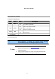
Rear Panel of N-WAP Physical Interface & Button Front Panel LED Indicators LED PWR LAN WPS Color Blue Yellow Red State Descriptions ON Access Point is power ON Off Access Point is power Off ON LAN is connected successfully Flashing Data is transmitting Off Ethernet not connected to PC ON WPS Active Off WPS Not Active Pressing over 5 seconds to reset to the factory default setting Reset Button Rear Panel Indicators RJ-45 connector, to maintain the existing network structure, LAN c
Chapter 2 Preparations & Installation Physical Installation Requirement 2 This chapter illustrates basic installation of Wireless Access Point (“Access Point” in the following term) Network cables. Use standard 10/100Base-TX network (UTP) cables with RJ-45 connectors. TCP/IP protocol must be installed on all PCs.
http://192.168.1.254 in the address bar of your web browser to logon Access Point web configuration page. To start Access Point web configuration, you must have one of these web browsers installed on computer for management Microsoft Internet Explorer 6.00 or higher with Java support ÍNote Please locate your PC in the same network segment (192.168.1.x) of Router.
Chapter 3 Network Settings Configuring and monitoring your Access Point from web browser 3 The Access Point integrates a web-based graphical user interface that can cover most configurations and machine status monitoring. Via standard web browser, you can configure and check machine status from anywhere around the world. Overview on the web interface of Access Point With web graphical user interface, you may have: More comprehensive setting feels than traditional command line interface.
Access Point login prompt screen When users login the web page, users can see the general information like company…etc in this main page.
Starting Setup in Web UI It is easy to configure and manage the AP/ Router with web browser. After successfully login, you can click Setup Wizard to quickly configure your AP/ Router. AP Mode Step 1. Set Wireless Network Name (SSID), and then click Next>>. Step 2. Select Wireless Security Mode. Step 3. Click the Finished button. You will then see the Finish page as shown below. The AP will reboot automatically to make your wireless configuration to take effect and finish the Setup. .
Client Mode Step 1. Set Wireless Network Name, or click Site Survey to scan the nearby AP. Step 2. Select Wireless Security Mode. Step 3. Click the Finished button. You will then see the Finish page as shown below.
The AP will reboot automatically to make your wireless configuration to take effect and finish the Setup. Router Mode Step 1. Select the WAN Access Type. Step 2. Enter the information for the selected WAN Access Type, and then click Next. If your access type is DHCP Client, then you can get the IP address from the ISP, so you do not need to enter the information like other modes. For other modes, please refer to the section WAN Interface Setup. Step 3. Click the Finished button.
Network Operation Mode You can setup different modes to WAN and LAN interface for NAT, Bridging and Wireless ISP function.
In this mode, all Ethernet ports are bridged together and NAT function AP is disabled. All the LAN port related function and firewall are not supported. In this mode, all Ethernet ports are bridged together and the wireless client will connect to ISP access point. The NAT is enabled and PCs in Client Ethernet ports share the same IP to ISP through wireless LAN. You must set the wireless to client mode first and connect to the ISP AP in Site-Survey page.
IP Address LAN IP Address of the Access Point Default : 192.168.1.254 Subnet Mask LAN mask of the Access Point Default : 255.255.255.0 DHCP Server You can select Server or Disable. If you select Disable, the DHCP service of LAN port is disabled. Default : Server DHCP Client Range The first and last IP address that DHCP server assigns. Default : 192.168.1.100 – 192.168.1.
DHCP Client Connections which use dynamic IP address assignment. Static IP Connections which use static IP address assignment. PPPoE WAN Access Type PPTP L2TP Connections which use PPPoE that requires a user name and password. Connections which use a Point-to-Point Tunneling Protocol (PPTP) connection. Connections which use a Layer2 Tunneling Protocol (L2TP) connection. Attain DNS Automatically Select to attain DNS automatically from your ISP.
DHCP Client If your ISP provides the DHCP service, please choose DHCP Client type, and the Router will automatically obtain IP parameters from your ISP. You can see the page as follows. The page includes the following fields: Object Host Name MTU Size Description This option specifies the Host Name of the Router. The default MTU (Maximum Transmission Unit) value is 1492 Bytes. It is not recommended that you change the default MTU Size unless required by your ISP.
The page includes the following fields: Object Description IP Address Enter the IP address in dotted-decimal notation provided by your ISP. Subnet Mask Enter the subnet Mask in dotted-decimal notation provided by your ISP, usually is 255.255.255.0 Default Gateway (Optional) Enter the gateway IP address in dotted-decimal notation provided by your ISP. MTU Size The normal MTU (Maximum Transmission Unit) value for most Ethernet networks is 1500 Bytes.
PPPoE If your ISP provides a PPPoE connection, select PPPoE option. User has to setup the user name and password according to the ISP that provided the related information. You can see the page as follows. The page includes the following fields: Object Description User Name Enter the User Name provided by your ISP. This field is case-sensitive. Password Enter the Password provided by your ISP. This field is case-sensitive. Service Name Enter the Internet service provider name in this field.
is 5 minutes. This function will be available when the Connection Type is selected to Connect on Demand. MTU Size The default MTU (Maximum Transmission Unit) value is 1452 Bytes. It is not recommended that you change the default MTU Size unless required by your ISP. PPTP If your ISP provides PPTP connection, please select PPTP option. And enter the following parameters. You can see the page as follows.
Subnet Mask Enter the subnet Mask in dotted-decimal notation provided by your ISP, usually is 255.255.255.0 Server IP Address Enter the PPTP Server IP address in dotted-decimal notation provided by your ISP. User Name Enter the User Name provided by your ISP. The Maximum input is 20 alphanumeric characters (case-sensitive). Password Enter the Password provided by your ISP. The Maximum input is 32 alphanumeric characters (case-sensitive).
The page includes the following fields: Object Description IP Address Enter the IP address in dotted-decimal notation provided by your ISP. Subnet Mask Enter the subnet Mask in dotted-decimal notation provided by your ISP, usually is 255.255.255.0 Server IP Address Enter the L2TP Server IP address in dotted-decimal notation provided by your ISP. User Name Enter the User Name provided by your ISP. The Maximum input is 20 alphanumeric characters (case-sensitive).
Manual from the drop-down menu. If selected Manual, user can click Connect button to make a connection. Idle Time It represents that the device will idle after the minutes you set. The time must be set between 1~1000 minutes. Default value of idle time is 5 minutes. This function will be available when the Connection Type is selected to Connect on Demand. MTU Size The default MTU (Maximum Transmission Unit) value is 1460 Bytes.
Chapter 4 Firewall Port Filtering Entries in this table are used to restrict certain types of data packets from your local network 4 to Internet through the Gateway. Use of such filters can be helpful in securing or restricting your local network.
Enable Port Filtering Check to enable Port Filtering function. Enter the beginning of the range of port numbers used by the service. If Port Range the service uses a single port number, enter it in both the start and finish fields. Protocol Comment Apply Changes Select the protocol (TCP, UDP or Both) used to the remote system or service. You may key in a description MAC address. After completing the settings on this page, click Apply Changes button to save the settings.
Enable IP Filtering Check to enable IP filtering function. Local IP Address Enter the local computer’s IP address. Protocol Comment Apply Changes Select the protocol (TCP, UDP or Both) used to the remote system or service. You may key in a description for the port range. After completing the settings on this page, click Apply Changes button to save the settings. Reset Click Reset button to restore to default values. Current Filter Table Shows the current IP filter information.
MAC Filtering Entries in this table are used to restrict certain types of data packets from your local network to Internet through the Gateway. Use of such filters can be helpful in securing or restricting your local network. Enable MAC Filtering Check to enable MAC filtering function. MAC Address Enter the client MAC address in the field. Comment You may key in a description MAC address. Apply Changes After completing the settings on this page, click Apply Changes button to save the settings.
web server or mail server on the private local network behind your Gateway's NAT firewall.
Enable Port Forwarding Check to enable Port Forwarding function. IP Address Enter the IP address in the field. Protocol Select the protocol (TCP, UDP or Both) used to the remote system or service. For TCP and UDP Services, enter the beginning of the range of port Port Range numbers used by the service. If the service uses a single port number, enter it in both the start and finish fields. Comment Apply Changes Reset Current Port Forwading Table You may key in a description MAC address.
Enable URL Filtering Check to enable URL filtering function. URL Address Enter the URL address in the field. Apply Changes After completing the settings on this page, click Apply Changes button to save the settings. Reset Click Reset button to restore to default values. Current Filter Table Shows the current URL address filter information. Delete Selected Click Delete All button to delete all the items. Reset Click Reset button to rest.
Check the box to enable DMZ function. If the DMZ Host Function is Enable DMZ enabled, it means that you set up DMZ host at a particular computer to be exposed to the Internet so that some applications/software, especially Internet / online game can have two way connections. DMZ Host IP Address Apply Changes Reset Enter the IP address of a particular host in your LAN which will receive all the packets originally going to the WAN port/Public IP address above.
Chapter 5 Wireless Settings Basic Settings This page is used to configure the parameters for wireless LAN clients who may connect to 5 your Access Point. Here you may change wireless encryption settings as well as wireless network parameters. Disable Wireless LAN Interface Band Enable or disable the wireless LAN. There are 6 modes: 2.4GHz (B), 2.4GHz (G), 2.4GHz (N), 2.4GHz (B+G), 2.4GHz (G+N), and 2.4GHz (B+G+N) mode. Default : 2.
Mode - AP: The AP functions as a wireless hub to which wireless clients can connect. The clients must make sure that they are configured to match the AP’s wireless settings. The AP must be connected to switch or other LAN segment patch cable. - WDS: WDS operation as defined by the IEEE802.11 standard has been made available. Using WDS it is possible to wirelessly connect Access Points, and in doing so extend a wired infrastructure to locations where cabling is not possible or inefficient to implement.
Domain Region The Domain Region decides what channels are available for your country. Please note that using the incorrect Domain Region is strictly prohibited. If you live in United States, you must use the FCC Domain Region. If you live inside EU, you must use ETSI domain. Domain Region Available Channels FCC (U.S.
WMM The short of Wi-Fi Multi-Media, it will enhance the data transfer performance of multimedia contents when they’re being transferred over wireless network. Default : Enable (Unavailable) Data Rate The Data Rate is the rate of data transmission for 802.11b/g/n clients. The Access Point will use the highest possible selected transmission rate to transmit the data packets.
- 39 -
Enable Multiple APs Check the checkbox to enable the Multiple AP/SSID. Up to 4 SSIDs for each BSS can be entered in the filed SSID. The name can be up to 32 characters. The same name (SSID) must be assigned to all wireless devices in your network. If Enable VLAN is checked, the wireless stations connecting to SSID of different VID can not communicate with each other. VLAN Settings Entries in below table are used to config vlan settings.
Enable VLAN VLAN (Virtual Local Area Network) refers to a group of logically networked devices on one or more LANs that are configured so that they can communicate as if they were attached to the same wire, when in fact they are located on different LAN segments. Because VLANs are based on logical instead of physical connections, it is very flexible for user/host management. VID Provide a number between 1 and 4090 for VLAN. This will cause the AP to send packets with VLAN tags.
Fragment Threshold “Fragment Threshold” specifies the maximum size of packet during the fragmentation of data to be transmitted. If you set this value too low, it will result in bad performance. Default : 2346 RTS Threshold When the packet size is smaller the RTS threshold, the access point will not use the RTS/CTS mechanism to send this packet. Default : 2347 Beacon Interval The interval of time that this access point broadcast a beacon. Beacon is used to synchronize the wireless network.
IAPP Inter-Access Point Protocol is a recommendation that describes an optional extension to IEEE 802.11 that provides wireless access-point communications among multivendor systems. Default : Enable Protection It is recommended to enable the protection mechanism. This mechanism can decrease the rate of data collision between 802.11b and 802.11g wireless stations.
Select SSID If assigned multiple AP feature, you could choose the SSID that want to setup encryption function. Encryption Select the data privacy algorithm you want. Enabling the security can protect your data while it is transferred from one station to another. Default : Disable 802.1x Authentication Check Box was used to switch the function of the 802.1X. When the 802.1X function is enabled, the Wireless user must authenticate to this router first to use the Network service.
- WPA When select the WPA function, the Wireless user must authenticate to this router first to use the Network service. RADIUS Server IP address or the 802.1X server’s domain-name. If you select HEX, you have to fill in 64 hexadecimal (0, 1, 2…8, 9, A, B…F) digits If ASCII, the length of pre-share key is from 8 to 63. Key value shared by the RADIUS server and this router. This key value is consistent with the key value in the RADIUS server.
- WPA-Mixed When select the WPA-Mixed function, the Wireless user must authenticate to this router first to use the Network service. RADIUS Server The router will detect automatically which Security type (WPA-PSK version 1 or 2) the client uses to encrypt. IP address or the 802.1X server’s domain-name. If you select HEX, you have to fill in 64 hexadecimal (0, 1, 2…8, 9, A, B…F) digits If ASCII, the length of Pre-share key is from 8 to 63. Key value shared by the RADIUS server and this router.
Access Control If you choose 'Allowed Listed', only those clients whose wireless MAC addresses are in the access control list will be able to connect to your Access Point. When 'Deny Listed' is selected, these wireless clients on the list will not be able to connect the Access Point. WDS Settings Wireless Distribution System uses wireless media to communicate with other APs, like the Ethernet does.
Site Survey This page provides tool to scan the wireless network. If any Access Point or IBSS is found, you could choose to connect it manually when client mode is enabled. WPS Settings Wi-Fi Protected Setup (WPS) is the simplest way to build connection between wireless network clients and this wireless router.
This wireless router supports two types of WPS: Push-Button Configuration (PBC), and PIN code. If you want to use PBC, you have to push a specific button on the wireless client to start WPS mode, and switch this wireless router to WPS mode too. You can push RET/WPS button of this wireless router, or click ‘Start PBC’ button in the web configuration interface to do this. If you want to use PIN code, you can see the setup as below.
1. Ensure you have set the security setting on Access Point (as Registrar). 2. Click the WPS button on Access Point (or the “Start PBC” button on the web interface of Access Point) and the other device (supports PBC function) in 2 minutes. 3. Access Point (Registrar) would send SSID and security key to the other device (Enrollee) through tunnel to connect. 4. If you see the wireless client in the list, WPS-PBC setting is successful. - PIN (as register) setup step: 1.
** As the figure as above, just change two roles. Wireless Schedule This page allows you setup the wireless schedule rule. Please do not forget to configure system time before enable this feature.
Chapter 6 Management Status In this page can show the current status and some basic settings of the Access Point. 6 Statistics This page shows the packet counters for transmission and reception regarding to Ethernet networks.
DDNS Choose menu “Dynamic DNS”, and you can configure the Dynamic DNS function when enabled router mode. The Router offers the DDNS (Dynamic Domain Name System) feature, which allows the hosting of a website, FTP server, or e-mail server with a fixed domain name (named by yourself) and a dynamic IP address, and then your friends can connect to your server by entering your domain name no matter what your IP address is. Before using this feature, you need to sign up for DDNS service providers such as www.
Current Time Input current time manually. Time Zone Select Select local time zone according to location. Enable NTP client Check to enable NTP update. Once this function is enabled, update Access Point will automatically update current time from NTP server. NTP server User may select prefer NTP sever or input address of NTP server manually.
Log This page can be used to set remote log server and show the system log.
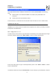
Enable Log Check to enable log function. System all Activates all logging functions. Wireless Only logs related to the wireless LAN will be recorded. DoS Only logs related to the DoS protection will be recorded. Enable Remote Log Only logs related to the Remote control will be recorded. Log Server IP Address Only logs related to the server will be recorded. Upgrade Firmware This page allows you upgrade the Access Point firmware to new version.
Firmware Version The current version is shown in this field. Browse and select file you want to upgrade and press Upload Select File to perform upgrade. Please wait till on screen shows related information after upgrade finished. Upload Reset Click the Upload button to perform the upgrade process. Click Reset will clean all current configurations and return to default values.
User Name Enter user name. New Password Input password for this user. Confirmed Password Confirm password again.
7 Chapter 7 QoS Enable QoS Use this section to configure QoS. The QoS settings improve your online gaming experience by ensuring that your game traffic is prioritized over other network traffic, such as FTP or Web. Enable QoS Check the box to enable the QoS function. Automatic Check the box to enable the automatic uplink/ download speed Uplink/Download Speed function. Manual Uplink/Download User can manually enter the uplink/ download speed in the blank Speed field.
Address Type Local IP Address Select IP or MAC address type. Depend on the address type that selected, user can enter the IP address or MAC address of client to set up the bandwidth of the MAC Address Mode transmission. Select Guaranteed minimum bandwidth or Restricted maximum bandwidth modes. Uplink Bandwidth (Kbps) Enter the Uplink Bandwidth (Kbps) in the column. Downlink Bandwidth (Kbps) Comment Enter the Downlink Bandwidth (Kbps) in the column. Enter the note for the setting.
8 Chapter 8 Route Setup Dynamic Route Dynamic routing performs the same function as static routing except it is steadier. Dynamic routing allows routing tables in routers to change as the possible routes change. There are several protocols used to support dynamic routing including RIP and OSPF. Enable Dynamic Route NAT Check the box to enable the Dynamic Route function. Network Address Translation (NAT) selects to enable or disable this function.
route Interface from LAN or WAN. Enable Static Route IP Address Subnet Mask Gateway Check the box to enable the Static Route function. Set up the IP address that would like to send the packets pass through. Set up the Subnet Mask that would like to send the packets pass through. Set up the gateway that would like to send the packets pass through.
It is used by a router to make routing decisions. The metrics used by a router to make routing decisions. It is typically one of many fields in a routing table. Router metrics can Metric contain any number of values that help the router determine the best route among multiple routes to a destination. A router metric typically based on information like path length, bandwidth, load, hop count, path cost, delay, Maximum Transmission Unit (MTU), reliability and communications cost.
Appendix A Frequently Asked Questions List If your Access Point is not functioning properly, you can refer to this chapter first for sample troubleshooting before contacting your dealer. This can save your time and effort but if the symptoms persist, please consult your dealer. Q1: I forget my Access Point login username and / or password A1: 1.) Restore Access Point to its factory default settings by pressing the “Reset” button which is at the side panel of the device for 5 seconds or more.
Appendix B Access Point Specifications (TBD) Product Model Hardware WLAN Standards Wireless Frequency Range Operation Mode Wireless Mode 802.11n Wireless Access Point N-WAP IEEE 802.11 b/g/n 2.4GHz ~ 2.4835 GHz AP, Client, Router AP, WDS and AP+WDS mode 64/128 bit WEP data encryption, WPA, WPA-PSK, WPA2, WPA2-PSK, Security WPA/WPA2 mix mode, 802.