4-slot Managed Modular Switch MGSW-004 User’s Manual
Trademarks Copyright PLANET Technology Corp. 2003. Contents subject to revision without prior notice. PLANET is a registered trademark of PLANET Technology Corp. to their respective owners. All other trademarks belong Disclaimer PLANET Technology does not warrant that the hardware will work properly in all environments and applications, and makes no warranty and representation, either implied or expressed, with respect to the quality, performance, merchantability, or fitness for a particular purpose.
TABLE OF CONTENTS CHAPTER 1 INTRODUCTION .................................................................................................. 1 1.1 CHECKLIST ........................................................................................................................ 1 1.2 ABOUT THE SWITCH ........................................................................................................... 1 1.3 PRODUCT FEATURE...................................................................................
.9 PORT SECURITY .............................................................................................................. 19 4.10 PRIORITY – 802.1P ........................................................................................................ 20 4.11 PRIORITY 2 – TOS (TYPE OF SERVICE)........................................................................... 20 4.12 IGMP..........................................................................................................................
Chapter 1 Introduction 1.1 Checklist Thank you for purchasing Planet’s MGSW-004 Managed Modular Switches. Before continuing, please check the contents of your package for following parts: Ø MGSW-004 Managed Modular Switches Ø Power Cord Ø RS-232 cable Ø CD-ROM Ø Rock mounting brackets Ø Four Robber foot Ø Quick installation Guide Ø Rock-mounting bracket Note: if any of these pieces are missing or damage please contact your dialer immediately. 1.
1.3 Product Feature Ø Ø Ø Conforms to IEEE 802.3, 802.3u, 802.3z, 802.3ab and 802.3x standards 4 expansion slots to configure flexible network One built-in intelligent module with RS-232 console port ( front side ) Ø Supports Half-duplex mode for backpressure, and full-duplex for flow-control Ø Store-and-Forward switching architecture for abnormal packet filtering Ø Up to 9.6Gbps Back-plane forwarding rate Ø Mac address: 4K for 8 port 10/100 TX and Gigabit module, 12K for 2/4/8 port fiber module.
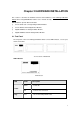
Chapter 2 HARDWARE INSTALLATION This section is describes the hardware features and installation of 4-slot Managed Modular Switch. Before using MGSW-004, read the user’s manual carefully. MGSW-004 has provide different modules Ø 8-Port 10/100 auto-sensing Intelligent Switch Module Ø 4-Port 100 Base-FX Intelligent Fiber Module Ø Gigabit 1000Base-T Intelligent Switch Module Ø Gigabit 1000Base-SX/LX Intelligent Fiber Module 2.
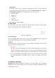
Console ports The RS-232 console port is an interface that directly connects to the PC. When the connection between the PC and switch is ready, run the Hyper Terminal and configure its communication parameters. The operating mode of the console port is: Ø Baud rate: 9600 Ø Data bits: 8 Ø Parity: none Ø Stop bits: 1 Ø Flow control: none After finished the setting, click OK. 2.
Desktop installation For desktop installation, make sure the desk is flat and clean. Plug all the network cables and the power cord then the system is ready. Note: Do not obstruct any vents at the sides of the case and keep water off. Rock-mount installation MGSW-004 can be mounted in a standard 19-inch rack. The following steps is teaching user how to Rack Mounting the Switch in the 19-inch rack: 1. Disconnect all cables from the switch. 2.
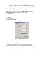
Chapter 3 Console and Telnet Management 3.1 connect To PC by RS-232 cable The RS-232 console port is an interface that directly connects to the PC. When the connection between the PC and switch is ready, run the Hyper Terminal and configure its communication parameters. The operating mode of the console port is: Ø Baud rate: 9600 Ø Data bits: 8 Ø Parity: none Ø Stop bits: 1 Ø Flow control: none After finished the setting, click OK. 3.2 Telnet To access the switch through Telnet 1.
3.3 Main Menu The main menu displays all the sub-menus that are available. Striking Enter, at a highlighted option, will confirm the choice of the specified sub-menu.
Ø System Name: display and change the system name of this Switch Ø System Location: display and set the location of this Switch Ø System Contact: display and set the administrator of this Switch Ø IP Address: display and set the IP address of MGSW-004 Ø Subnet Mask: display and set the Subnet Mask of MGSW-004 Ø Default Gateway: display and set the gateway of MGSW-004 Ø Change User/Password: allow to set the User name and password Ø Console Login Enabled: provide enable or disable Console logi
3.3.3 Address Table This menu contains four items for MAC address record on each working port Ø Ø Ø Ø All Module Module Port Quit 3.3.
3.3.5 Broadcast Storm Filter This menu contains three items to enable or disable Broadcast Storm Filter: Ø Enable Ø Disable Ø Quit 3.3.6 IGMP This menu contains three items to enable or disable IGMP: Ø Enable Ø Disable Ø Quit 3.3.7 VLAN Mode (2 modes) This menu contains two items for 2 VLAN mode selections: Ø VLAN is valid for all packets Disable Ø VLAN is valid for broadcast and multicast packets, not for unicast packets.
3.3.8 VLAN for CPU (2 VLANs) This menu contains two items for 2 VLANs for CPU: Ø Current first VLAN for CPU: VLAN ID 1Current second Ø VLAN for CPU: None Ø Quit 3.3.9 Secure IP for Telnet and HTTP This menu contains seven items for Secure IP setting: Ø Secure IP for Telnet: Disabled (default value) Ø Secure IP for HTTP: Disabled (default value) Ø Secure IP 1: Ø Secure IP 2: Ø Secure IP 3: Ø Secure IP 4: Ø Quit 3.3.9.
MGSW-004 3.3.9.3 Secure IP 1,2,3,4 Allow setting 4 Secure IP addresses of 4 PCs 3.3.10 Save Current Settings This menu provide save current settings of this Switch. 3.3.11 Factory Default Settings & Reboot System This menu provide restore to the default settings of this Switch 3.3.
3.3.
Chapter 4 WEB MANAGEMENT MGSW-004 support web management therefore in this section will introduce the configuration and functions of the web-based management. Before to use web management, please setup the IP Address with the console port (RS-232) and use this IP address to configure MGSW-004 through the web interface or modify your PC’s IP domain to the same with MGSW-004 then use the default IP address to remote configure MGSW-004 through the Web interface. 4.
4.2 Home The homepage is display the configuration of the MGSW-004 System Name An administratively-assigned name of the managed unit System Location The physical location of this managed unit System Contact The contact person for this managed unit.
4.5 Statistics (Port Counters) and Statistics 2 (RMON Statistics) The Statistic page displays the detailed information about each port. You can compare and evaluate throughput or other port parameters. All screen data is updated automatically .You can clear 8 counters or packet seize counters of some ports by select the corresponding "Clear" check boxes then press "Clear" button. To clear all counters of all ports, press the "Select All" button then "Clear" button.
4.6 VLAN A VLAN (Virtual LAN) is a group of switch ports designated by the switch as belonging to the same broadcast domain. This feature allows workgroup to be defined on the basis of their logical location instead of their physical location, and does not require recalling The default VLAN is that all ports belong to VLAN 1. This switch support up to 4095 port-based 802.1Q-compatible virtual LANs (VLANs). In the VLAN management window, you will see 2 VLANs in the page.
You can add, edit and remove port members of each trunk and then press "Apply" button after you have finished configuring the trunks you need. (Note: Make sure trunking ports are in the same VLAN group. ) 4.8 STP Spanning tree is a link management protocol that provides path redundancy while preventing undesirable loops in the network. For Layer 2 Ethernet network to function properly, only one active path must exist between two stations.
If you want to participate in spanning tree, have the "Enable Spanning Tree Protocol" checkbox selected. The Current Spanning Tree Root describes the unique root switch information for the instance of spanning tree.
there is no MAC address count restriction for that port. Ø Type the number in the “ Max Allowed MAC Address Count “ edit for that port. The upper bound of this number is the “ Max Allowed MAC Address Count per port “ Ø Press the “ Press “ button Ø The “ Used Count “ will tell you how many MAC address residing in the corresponding port now. Note: A trunked port is not allowed to enable the port security option. 4.10 Priority – 802.1p There are two priority queues (high and low) on each port.
IF this function of a port is enabled, then the most significant 6 bits of the TOS (these 6 bits are also known as the DiffServ Code Point "DSCP" field, value from 0 to 63) are used to assign a priority to the packet received from this port. Please check the corresponding mapping checkbox to assign a high priority or uncheck that to assign a low priority. 4.12 IGMP IGMP is used in multicast communication network applications where one or more servers, for example, video servers, generate multicast traffic.
4.13 Static Address In this function, you can lock a certain MAC address (associated with a host) to a certain port. Once a certain MAC address is locked to a certain port, this MAC address will not receive any packets if it is moved to another port Static addresses are manually entered into the Static Address Table Ø Enter the MAC address in the MAC Address field (ex.
4.15 Port Mirror If you want to monitor all receive and transmit packets of one port. You can do the following: Ø Choose the monitored port in "Mirror Source Port" choice box in the corresponding mirror source module. Only one port can be monitored in one module at the same time Ø Choose the corresponding target module, port in "Mirror Target Module" and "Mirror Target Port" choice box. Ø Click the corresponding "Enabled" check box.
4.16 IP Config You can change the IP address, subnet mask and default gateway of the managed node. (You can also do that from RS232 console).
4.17 SNMP You can manage the Switch using third-party’s SNMP (Simple Network Management Protocol) agent. Access rights to the SNMP agent are controlled by community strings. To set system name, system location and system contact, you can type the desired text string in the corresponding edit box. 4.18 Save & Reboot You can save current settings by click the "Current Settings" checkbox then press the "Apply" button next to the checkbox.
4.19 Upgrade You can on-line upgrade the firmware of the managed unit. The following steps is needed to upgrade the firmware: Ø Use HTTP or FTP to download the new version firmware from our website. Ø Enter password in the "Password" edit box. Ø Enter the file downloaded in the "File Path" edit box. (You can use "Browse" button to select the file.) Ø Press the "Upgrade" button.
Appendix A Technical Specifications Model Ports Dimensions MGSW-004 4 module slot RS-232 DB-9 male 440mm x 227mm x 67mm Weight Power Requirement Switch architecture Flow Control Modules Model 4.6kg 100-240 VAC 50-60Hz MGSW-8TP Speed per port 10/100Mbps Auto-negotiation Media type Store-and-forward, Back-plane 9.6Gbs Back pressure for half duplex, IEEE 802.
Appendix B Cable Specification 10/100Mbps, 10/100Base-TX Contact MDI MDI-X 1 1 3 2 2 6 3 3 1 6 6 2 Straight-Through Cable Crossover Cable 1000Mbps, 1000Base T Contact MDI MDI-X 1 BI_DA+ BI_DB+ 2 BI_DA- BI_DB- 3 BI_DB+ BI_DA+ 4 BI_DC+ BI_DD+ 28
5 BI_DC- BI_DD- 6 BI_DB- BI_DA- 7 BI_DD+ BI_DC+ 8 BI_DD- BI_DC- 29