
User's Manual
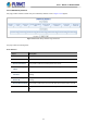
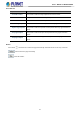
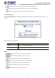
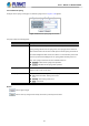
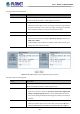
Table Of Contents
- 1. INTRODUCTION
- 2. INSTALLATION
- 3. SWITCH MANAGEMENT
- 4. WEB CONFIGURATION
- 4.1 Main Web page
- 4.2 System
- 4.2.1 Management
- 4.2.1.1 System Information
- 4.2.1.2 IP Configuration
- 4.2.1.3 IP Status
- 4.2.1.4 ARP Table
- 4.2.1.5 Users Configuration
- 4.2.1.6 Privilege Levels
- 4.2.1.7 NTP Configuration
- 4.2.1.7.1 System Time Correction Manually
- 4.2.1.8 Time Configuration
- 4.2.1.9 UPnP
- 4.2.1.10 DHCP Relay
- 4.2.1.11 DHCP Relay Statistics
- 4.2.1.12 CPU Load
- 4.2.1.13 System Log
- 4.2.1.14 Detailed Log
- 4.2.1.15 Remote Syslog
- 4.2.1.16 SMTP Configuration
- 4.2.1.17 Fault Alarm
- 4.2.1.18 Digital Input/Output
- 4.2.2 Simple Network Management Protocol
- 4.2.3 RMON
- 4.2.4 DHCP server
- 4.2.5 Remote Management
- 4.2.1 Management
- 4.3 Switching
- 4.3.1 Port Management
- 4.3.2 Link Aggregation
- 4.3.3 VLAN
- 4.3.3.1 VLAN Overview
- 4.3.3.2 IEEE 802.1Q VLAN
- 4.3.3.3 VLAN Port Configuration
- 4.3.3.4 VLAN Membership Status
- 4.3.3.5 VLAN Port Status
- 4.3.3.6 Private VLAN
- 4.3.3.7 Port Isolation
- 4.3.3.8 VLAN setting example:
- 4.3.3.9 MAC-based VLAN
- 4.3.3.10 IP Subnet-based VLAN Membership Configuration
- 4.3.3.11 Protocol-based VLAN
- 4.3.3.12 Protocol-based VLAN Membership
- 4.3.2.13 VLAN Translation
- 4.3.4 Spanning Tree Protocol
- 4.3.5 Multicast
- 4.3.6 MLD Snooping
- 4.3.7 MVR (Multicast VLAN Registration)
- 4.3.8 LLDP
- 4.3.9 MAC Address Table
- 4.3.10 Loop Protection
- 4.3.11 UDLD
- 4.3.12 GVRP
- 4.3.13 PTP
- 4.3.14 Link OAM
- 4.4 Quality of Service
- 4.4.2 Bandwidth Control
- 4.4.4.2 DSCP-based QoS
- 4.5 Security
- 4.6 Ring
- 4.7 Maintenance
- 5. COMMAND LINE MODE
- 6. SWITCH OPERATION
- 7. TROUBLESHOOTING
- APPENDIX A: Networking Connection
- APPENDIX B : GLOSSARY

User’s Manual of MGSD-10080F
80
The page includes the following fields:
Object Description
• Enable
Check the Enable checkbox to enable Digital Input function.
Uncheck the Enable checkbox to disable Digital Input function.
• DI Condition
As Digital Input:
Allows user to select High to Low or Low to High. This means a signal received
by system is from High to Low or From Low to High. It will trigger an action that
logs a customize message or issue the message from the switch.
• Event Description
Allows user to set a customized message for Digital Input function alarming.
• Action
As Digital Input:
Allows user to record alarm message to System log, syslog or issues out via
SNMP Trap or SMTP.
As default SNMP Trap and SMTP are disabled, please enable them first if you
want to issue alarm message via them.
Figure 4-2-22: Digital Output Control Configuration page Screenshot
The page includes the following fields:
Object Description
• Enable
Check the Enable checkbox to enable Digital Output function.
Uncheck the Enable checkbox to disable Output function.
• Action
As Digital Output:
Allows user to monitor an alarm from port failure, power failure, Digital Input
0 (DI 0) and Digital Input 1(DI 1) which means if Digital Output has detected
these events, then Digital Output would be triggered according to the setting of
Condition.
• DI Condition
As Digital Output:
Allows user to select High to Low or Low to High. This means
that when the
switch is power-failed or port-failed, then system will issue a High or