
User's Manual
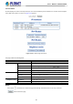
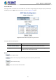
Table Of Contents
- 1. INTRODUCTION
- 2. INSTALLATION
- 3. SWITCH MANAGEMENT
- 4. WEB CONFIGURATION
- 4.1 Main Web page
- 4.2 System
- 4.2.1 Management
- 4.2.1.1 System Information
- 4.2.1.2 IP Configuration
- 4.2.1.3 IP Status
- 4.2.1.4 ARP Table
- 4.2.1.5 Users Configuration
- 4.2.1.6 Privilege Levels
- 4.2.1.7 NTP Configuration
- 4.2.1.7.1 System Time Correction Manually
- 4.2.1.8 Time Configuration
- 4.2.1.9 UPnP
- 4.2.1.10 DHCP Relay
- 4.2.1.11 DHCP Relay Statistics
- 4.2.1.12 CPU Load
- 4.2.1.13 System Log
- 4.2.1.14 Detailed Log
- 4.2.1.15 Remote Syslog
- 4.2.1.16 SMTP Configuration
- 4.2.1.17 Fault Alarm
- 4.2.1.18 Digital Input/Output
- 4.2.2 Simple Network Management Protocol
- 4.2.3 RMON
- 4.2.4 DHCP server
- 4.2.5 Remote Management
- 4.2.1 Management
- 4.3 Switching
- 4.3.1 Port Management
- 4.3.2 Link Aggregation
- 4.3.3 VLAN
- 4.3.3.1 VLAN Overview
- 4.3.3.2 IEEE 802.1Q VLAN
- 4.3.3.3 VLAN Port Configuration
- 4.3.3.4 VLAN Membership Status
- 4.3.3.5 VLAN Port Status
- 4.3.3.6 Private VLAN
- 4.3.3.7 Port Isolation
- 4.3.3.8 VLAN setting example:
- 4.3.3.9 MAC-based VLAN
- 4.3.3.10 IP Subnet-based VLAN Membership Configuration
- 4.3.3.11 Protocol-based VLAN
- 4.3.3.12 Protocol-based VLAN Membership
- 4.3.2.13 VLAN Translation
- 4.3.4 Spanning Tree Protocol
- 4.3.5 Multicast
- 4.3.6 MLD Snooping
- 4.3.7 MVR (Multicast VLAN Registration)
- 4.3.8 LLDP
- 4.3.9 MAC Address Table
- 4.3.10 Loop Protection
- 4.3.11 UDLD
- 4.3.12 GVRP
- 4.3.13 PTP
- 4.3.14 Link OAM
- 4.4 Quality of Service
- 4.4.2 Bandwidth Control
- 4.4.4.2 DSCP-based QoS
- 4.5 Security
- 4.6 Ring
- 4.7 Maintenance
- 5. COMMAND LINE MODE
- 6. SWITCH OPERATION
- 7. TROUBLESHOOTING
- APPENDIX A: Networking Connection
- APPENDIX B : GLOSSARY

User’s Manual of MGSD-10080F
54
client devices on the network.
• IP Interface Delete
Select this option to delete an existing IP interface.
VLAN
The VLAN associated with the IP interface. Only ports in this VLAN
will be able to access the IP interface. This field is only available for
input when creating a new interface.
IPv4
DHCP
Enabled
Enable the DHCP client by checking this box.
Fallback
The number of seconds for trying to obtain a DHCP lease.
Current
Lease
For DHCP interfaces with an active lease, this column shows the
current interface address, as provided by the DHCP server.
IPv4 Address
Provide the IP address of this Managed Metro Switch in dotted
decimal notation.
Mask Length
The IPv4 network mask, in number of bits (prefix length). Valid values
are between 0 and 30 bits for an IPv4 address.
DHCPv6 Enable
Enable the DHCPv6 client by checking this box. If this option is
enabled, the system will configure the IPv6 address of the interface
using the DHCPv6 protocol
Rapid
Commit
Enable the DHCPv6 Rapid-Commit option by checking this box. If
this option is enabled, the DHCPv6 client terminates the waiting
process as soon as a Reply message with a Rapid Commit option is
received.
This option is only manageable when DHCPv6 client is enabled.
Current
Lease
For DHCPv6 interface with an active lease, this column shows the
interface address provided by the DHCPv6 server
IPv6 Address
Provide the IP address of this Managed Metro Switch. An IPv6
address is in 128-bit records represented as eight fields of up to four
hexadecimal digits with a colon separating each field (:).
Mask Length
The IPv6 network mask, in number of bits (prefix length). Valid values
are between 1 and 128 bits for an IPv6 address.
• IP Routes Delete
Select this option to delete an existing IP route.
Network
The destination IP network or host address of this route. Valid format
is dotted decimal notation or a valid IPv6 notation. A default route can
use the value 0.0.0.0 or IPv6 :: notation.
Mask Length
The destination IP network or host mask, in number of bits (prefix
length).
Gateway
The IP address of the IP gateway. Valid format is dotted decimal
notation or a valid IPv6 notation. Gateway and Network must be of
the same type.
Next Hop VLAN
The VLAN ID (VID) of the specific IPv6 interface associated with the
gateway.