
User's Manual
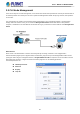
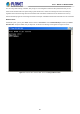
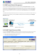
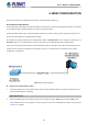
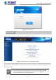
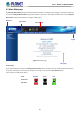
Table Of Contents
- 1. INTRODUCTION
- 2. INSTALLATION
- 3. SWITCH MANAGEMENT
- 4. WEB CONFIGURATION
- 4.1 Main Web page
- 4.2 System
- 4.2.1 Management
- 4.2.1.1 System Information
- 4.2.1.2 IP Configuration
- 4.2.1.3 IP Status
- 4.2.1.4 ARP Table
- 4.2.1.5 Users Configuration
- 4.2.1.6 Privilege Levels
- 4.2.1.7 NTP Configuration
- 4.2.1.7.1 System Time Correction Manually
- 4.2.1.8 Time Configuration
- 4.2.1.9 UPnP
- 4.2.1.10 DHCP Relay
- 4.2.1.11 DHCP Relay Statistics
- 4.2.1.12 CPU Load
- 4.2.1.13 System Log
- 4.2.1.14 Detailed Log
- 4.2.1.15 Remote Syslog
- 4.2.1.16 SMTP Configuration
- 4.2.1.17 Fault Alarm
- 4.2.1.18 Digital Input/Output
- 4.2.2 Simple Network Management Protocol
- 4.2.3 RMON
- 4.2.4 DHCP server
- 4.2.5 Remote Management
- 4.2.1 Management
- 4.3 Switching
- 4.3.1 Port Management
- 4.3.2 Link Aggregation
- 4.3.3 VLAN
- 4.3.3.1 VLAN Overview
- 4.3.3.2 IEEE 802.1Q VLAN
- 4.3.3.3 VLAN Port Configuration
- 4.3.3.4 VLAN Membership Status
- 4.3.3.5 VLAN Port Status
- 4.3.3.6 Private VLAN
- 4.3.3.7 Port Isolation
- 4.3.3.8 VLAN setting example:
- 4.3.3.9 MAC-based VLAN
- 4.3.3.10 IP Subnet-based VLAN Membership Configuration
- 4.3.3.11 Protocol-based VLAN
- 4.3.3.12 Protocol-based VLAN Membership
- 4.3.2.13 VLAN Translation
- 4.3.4 Spanning Tree Protocol
- 4.3.5 Multicast
- 4.3.6 MLD Snooping
- 4.3.7 MVR (Multicast VLAN Registration)
- 4.3.8 LLDP
- 4.3.9 MAC Address Table
- 4.3.10 Loop Protection
- 4.3.11 UDLD
- 4.3.12 GVRP
- 4.3.13 PTP
- 4.3.14 Link OAM
- 4.4 Quality of Service
- 4.4.2 Bandwidth Control
- 4.4.4.2 DSCP-based QoS
- 4.5 Security
- 4.6 Ring
- 4.7 Maintenance
- 5. COMMAND LINE MODE
- 6. SWITCH OPERATION
- 7. TROUBLESHOOTING
- APPENDIX A: Networking Connection
- APPENDIX B : GLOSSARY

User’s Manual of MGSD-10080F
46
4. WEB CONFIGURATION
This section introduces the configuration and functions of the Web-based management.
About Web-based Management
The Managed Metro Switch offers management features that allow users to manage the Managed Metro Switch from anywhere
on the network through a standard browser such as Microsoft Internet Explorer.
The Managed Metro Switch can be configured through an Ethernet connection, making sure the manager PC must be set on
the same IP subnet address as the Managed Metro Switch.
For example, the default IP address of the Managed Metro Switch is 192.168.0.100, then the manager PC should be set at
192.168.0.x (where x is a number between 1 and 254, except 100), and the default subnet mask is 255.255.255.0.
If you have changed the default IP address of the Managed Metro Switch to 192.168.1.1 with subnet mask 255.255.255.0 via
console, then the manager PC should be set at 192.168.1.x (where x is a number between 2 and 254) to do the relative
configuration on manager PC.
Figure 4-1-1: Web Management
Logging on the Managed Metro Switch
1. Use Internet Explorer 8.0 or above Web browser. Enter the factory-default IP address to access the Web interface. The
factory-default IP Address as following:
https://192.168.0.100
2. When the following login screen appears, please enter the default username "admin" with password “admin” (or the
username/password you have changed via console) to login the main screen of Managed Metro Switch. The login screen
in Figure 4-1-2 appears.